EPSON AcuLaser CX11/CX11F Revision B
TROUBLESHOOTING Printer 222
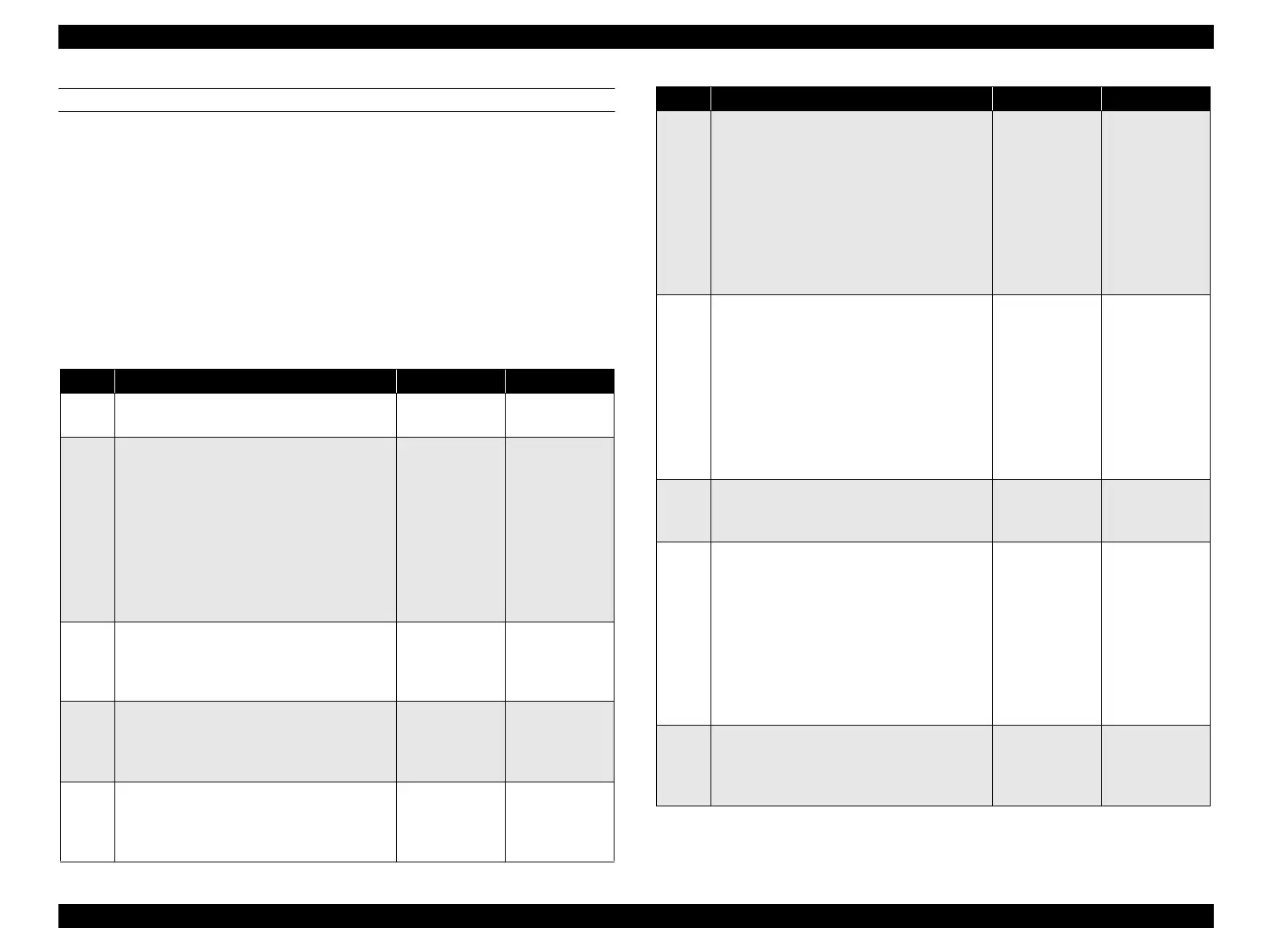
FIP-51
Panel Message
Service Req E547
Possible parts that caused the error
Troubleshooting
HARNESS-ASSY FEED MAIN DRIVE ASSY FEED
PWBA TRAY 500 HARNESS-ASSY FEED 1
HARNESS ASSY MAIN PWBA MCU
LV/HVPS
Step Check Yes No
1
Check of DRIVE ASSY FEED attachment
Is DRIVE ASSY FEED attached correctly?
Go to Step [2]. Re-attach, and go
to step [2].
2
Continuity check of HARNESS-ASSY FEED
MAIN
Disconnect P/J437 from PWBA TRAY CONT.
Do all of the wiring below have normal
continuity?
J437-1 ↔ CN1-5
J437-2 ↔ CN1-4
J437-4 ↔ CN1-2
J437-5 ↔ CN1-1
Go to Step [3]. Replace
HARNESS-
ASSY FEED
MAIN.
3
24 VDC power supply check to DRIVE
ASSY FEED
The voltage of P440-2 ↔ P440-1 on PWBA
FEED DRV is 24 VDC?
Go to Step [4]. Go to Step [5].
4
Check of FEED MOTOR START signal
The voltage of P440-5 ↔ P440-1 on PWBA
FEED DRV is xx VDC when FEED MOTOR
START signal is ON?
Replace DRIVE
ASSY FEED.
(p.454)
Go to Step [10].
5
24 VDC power supply check to PWBA
TRAY 500
The voltage of P435-9/10 ↔ P435-7/8 on
PWBA TRAY 500 is 24 VDC?
Replace PWBA
TRAY 500.
(p.452)
Go to Step [6].
6
Continuity check of HARNESS-ASSY FEED 1
Disconnect P/J435 from PWBA TRAY CONT.
Do all of the wiring below have normal
continuity?
J435-10 ↔ P608-1 (connector on Feeder to
be connected to the printer)
J435-9 ↔ P608-2
J435-8 ↔ P608-3
J435-7 ↔ P608-4
Go to Step [7]. Replace PWBA
TRAY 500.
(p.452)
7
Continuity check of HARNESS ASSY MAIN
Disconnect P/J421 from PWBA MCU.
Do all of the wiring below have normal
continuity?
J421-1 ↔ J608-10 (connector on the printer
to connect Feeder)
J421-2 ↔ J608-9
J421-3 ↔ J608-8
J421-4 ↔ J608-7
Go to Step [8]. Repair broken or
shorted part.
8
24 VDC power supply check to PWBA MCU
The voltage of P410-5/6 ↔ P410-7/8 on
PWBA MCU is 24 VDC?
Replace PWBA
MCU. (p.432)
Go to Step [9].
9
Continuity check of HARNESS ASSY MAIN
Disconnect P/J410 from PWBA MCU and P/
J502 from LV/HVPS.
Do all of the wiring below have normal
continuity?
J410-5 ↔ J502-5
J410-6 ↔ J502-6
J410-7 ↔ J502-7
J410-8 ↔ J502-8
Replace LV/
HVPS. (p.435)
Repair broken or
shorted part.
10
5 VDC power supply check to PWBA TRAY
500
The voltage of P435-6 ↔ P435-5 on PWBA
TRAY CONT is 5 VDC?
Replace PWBA
TRAY 500.
(p.452)
Go to Step [11].
Step Check Yes No
manuals4you.commanuals4you.com
 Loading...


