EPSON AcuLaser CX11/CX11F Revision B
TROUBLESHOOTING Printer 181
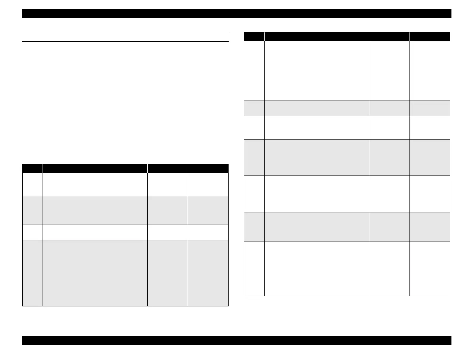
FIP-27
Panel Message
Jam MP, E
Possible parts that caused the error
Troubleshooting
ROLL MSI HOLDER ASSY RETARD MSI
CHUTE ASSY PAPER GUIDE ROLL ASSY-PRE REGI
ROLL-PINCH ACTUATOR-REGI.
SENSOR REGI HARNESS-ASSY P/H1
HARNESS-ASSY P/H2 PWBA MCU
LV/HVPS MOTOR-PH
HARNESS ASSY MAIN CLUTCH ASSY PRE REGI
Step Check Yes No
1
Check of the paper
Is the paper loaded in the paper tray wrinkled or
torn?
Replace with
new, dry paper.
Go to Step [2].
2
Paper size setting check
Does the size of the paper in use match the size
of the paper set on the control panel?
Go to Step [4]. Change the paper
size setting, and
proceed to step
[3].
3
Does the error recur when a test print is
made?
Go to Step [4]. End of procedure
4
Shape and operation check of ROLL ASSY
of MSI section
Remove MSI. (p.329)
Are ROLL MSI, HOLDER ASSY RETARD
MSI, CHUTE ASSY PAPER GUIDE, and
other parts attached correctly?
Also, do these parts rotate smoothly without
any dirt or damage?
Turn by hand to check.
Go to Step [5]. Replace ROLL
ASSY in
question.
5
Shape and operation check of ROLL ASSY-
PRE REGI and ROLL-PINCH
Open CHUTE ASSY-REAR.
Are ROLL ASSY-PRE REGI and ROLL-
PINCH attached correctly?
Also, do these parts rotate smoothly without
any dirt or damage?
Turn by hand to check.
Go to Step [6]. Replace ROLL in
question.
6
Does the error recur when a test print is
made?
Go to Step [7]. End of procedure
7
Check of the paper position
Is the leading edge of the paper passing through
PRE REGI ROLL?
Go to Step [8]. Go to Step [20].
8
Operation check of ACTUATOR-REGI
Does ACTUATOR-REGI move smoothly
without any damage? Does it enter the sensor
sensing area when there is paper? Does it leave
the sensor sensing area when there is no paper?
Go to Step [9]. Replace
ACTUATOR-
REGI. (p.360)
9
Operation check of SENSOR REGI
The voltage of P408-12 ↔ P408-11 on PWBA
MCU is 0 VDC when ACTUATOR REGI
enters the sensor sensing area, and is 5 VDC
when it leaves the sensing area?
Go to Step [15]. Go to Step [10].
10
5 VDC power supply check to SENSOR
REGI
The voltage of P408-10 ↔ P408-11 on PWBA
MCU is 5 VDC?
Go to Step [11]. Go to Step [13].
11
Continuity check of HARNESS-ASSY P/H1
Disconnect the P/J408 from PWBA MCU.
Do all of the wiring below have normal
continuity?
J408-10 ↔ J603-3
J408-11 ↔ J603-2
J408-12 ↔ J603-1
Go to Step [12]. Replace
HARNESS-
ASSY P/H1.
Step Check Yes No
 Loading...


