EPSON AcuLaser CX11/CX11F Revision B
DISASSEMBLY AND ASSEMBLY Printer 376
4.2.5.5 CAM ASSY-2ND
REMOVAL
1. Remove COVER ASSY RH. (p326)
2. Remove CHUTE ASSY-FSR and COVER ASSY-RR 2ND. (p366)
3. Remove 2ND BTR ASSY. (p374)
4. Remove PLATE BIAS-2ND ASSY. (p384)
5. Remove SENSOR 2BTR RETRACT. (p382)
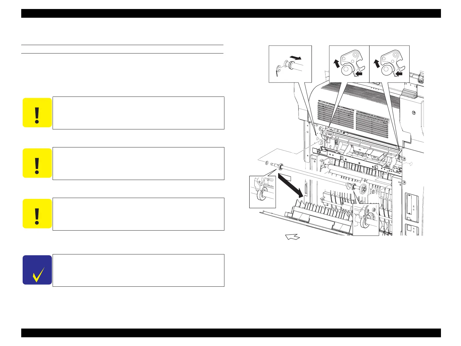
6. Remove the E-ring fastening the right-side shaft on CAM ASSY-2ND to the main
unit, and slide BEARING to the left.
7. Temporarily slide CAM ASSY-2ND to the right, and draw out the shaft on CAM
ASSY-2ND from the left-side bearing on the main unit, and remove CAM ASSY-
2ND together with BEARING.
8. Remove BEARING from CAM ASSY-2ND.
Figure 4-65. Removal of CAM ASSY-2ND
C A U T I O N
When performing the following work, there is no need to remove
WIRE ASSY 2BTR from PLATE BIAS-2ND ASSY.
C A U T I O N
When performing the following work, there is no need to remove
SENSOR 2BTR RETRACT from BRACKET-SENSOR PHOTO.
C A U T I O N
When performing the following work, take care not to drop or lose
BEARING.
C H E C K
P O I N T
When performing the following work, work can be performed more
easily by pressing FRAME ASSY-2ND in the direction of the arrow,
and releasing FRAME ASSY-2ND from the cam on CAM ASSY-
2ND.
Leg_Sec03_148RB
CAUTION
CAUTION
CHECK POINT CHECK POINT
8)
6)-1
6)-2
7)-1 7)-1
7)-2
RIGHT
8)
manuals4you.commanuals4you.com
 Loading...


