EPSON AcuLaser CX11/CX11F Revision B
TROUBLESHOOTING Printer 206
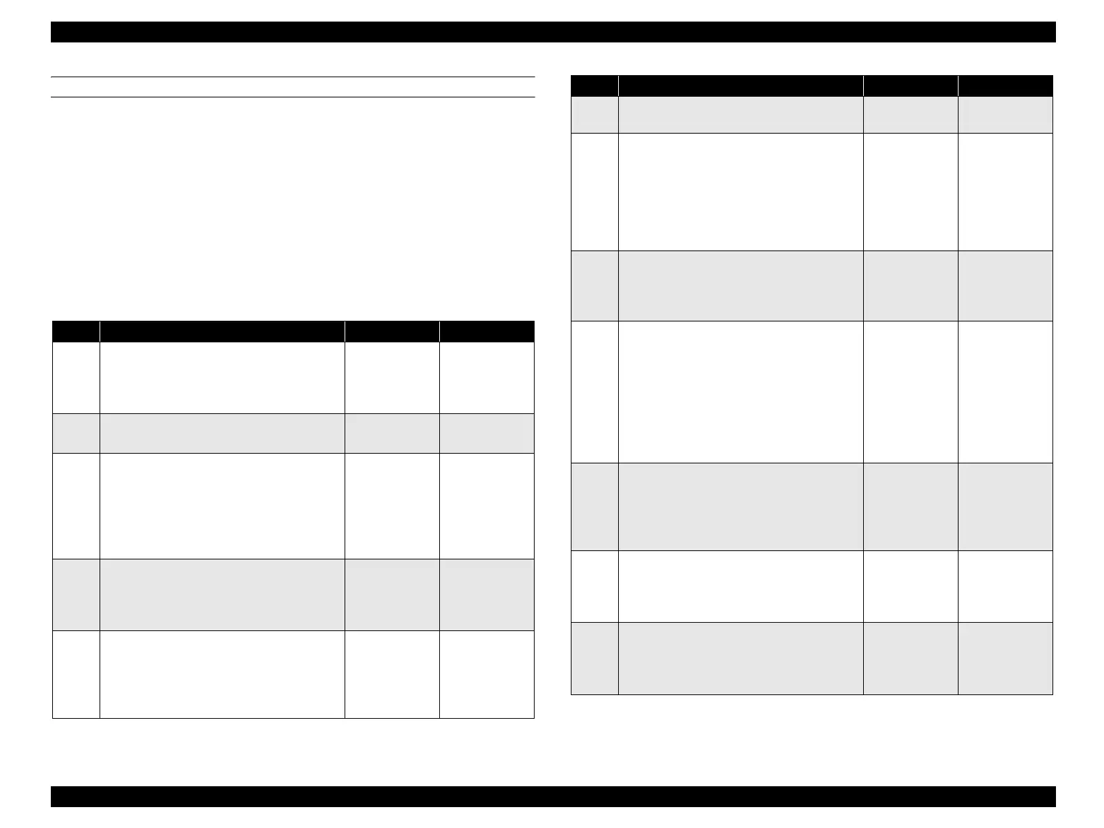
FIP-39
Panel Message
Service Req E511
Possible parts that caused the error
Troubleshooting
Photoconductor Unit SENSOR TR-0
HARNESS-ASSY XERO MOTOR ASSY P/R
HARNESS ASSY MAIN PWBA MCU
LV/HVPS
Step Check Yes No
1
Check of Photoconductor Unit attachment
Re-attach Photoconductor Unit.
Does the error recur when the power is turned
ON?
Go to Step [2]. End of procedure
2
Operation check of Photoconductor Unit
Is the Drum of Photoconductor Unit rotating?
Go to Step [3]. Go to Step [10].
3
Check for dirt on silver seal on Belt in
Photoconductor Unit
Remove Photoconductor Unit.
Turn gear of Photoconductor Unit until silver
seal attached to Belt can be seen.
Is silver seal dirty?
Replace
Photoconductor
Unit.
Go to Step [4].
4
Check of SENSOR TR-0 (TR0 Sensor)
attachment
Remove Photoconductor Unit.
Is SENSOR TR-0 attached securely?
Go to Step [5]. Re-attach
the SENSOR TR-
0, and go to step
[5].
5
Check of dirt and foreign bodies on surface
of SENSOR TR-0
Remove Photoconductor Unit.
Are there any dirt or foreign bodies on the
SENSOR TR-0 surface?
Clean to remove
any dirt or
foreign bodies,
and go to step
[6].
Go to Step [7].
6
Does the error recur when the power is
turned ON?
Go to Step [7]. End of procedure
7
Operation check of SENSOR TR-0
Remove Photoconductor Unit.
The voltage of P416-2 ↔ P416-3 on PWBA
MCU is 5 VDC when silver paper or other
reflective object comes close to the sensing area
of SENSOR TR-0, and is 0 VDC when the
object is released?
Replace PWBA
MCU. (p.432)
Go to Step [8].
8
Check of 5 VDC power supply to SENSOR
TR-0
The voltage of P416-1 ↔ P416-3 on PWBA
MCU is 5 VDC?
Go to Step [9]. Go to Step [14].
9
Continuity check of HARNESS-ASSY
XERO
Disconnect the P/J416 from PWBA MCU.
Do all of the wiring below have normal
continuity?
J416-1 ↔ J108-3
J416-2 ↔ J108-2
J416-3 ↔ J108-1
Replace
SENSOR TR-0.
(p.387)
Replace
HARNESS-
ASSY XERO.
10
Check after replacement of MOTOR ASSY
P/R
Replace MOTOR ASSY P/R. (p.426)
Does the error recur when the power is turned
ON?
Go to Step [11]. End of procedure
11
24 VDC power supply check to MOTOR
ASSY P/R
Disconnect P/J201 from MOTOR ASSY P/R.
The voltage of J201-1 ↔ J201-2 is 24 VDC?
Go to Step [12]. Go to Step [13].
12
Continuity check of HARNESS ASSY MAIN
Disconnect the P/J403 from PWBA MCU.
Is the continuity normal between all terminals
of J403 ↔ J200?
Replace PWBA
MCU. (p.432)
Repair broken or
shorted part.
Step Check Yes No
manuals4you.commanuals4you.com
 Loading...


