EPSON AcuLaser CX11/CX11F Revision B
DISASSEMBLY AND ASSEMBLY Printer 420
4.2.10 DRIVE
4.2.10.1 DRIVE ASSY BTR
REMOVAL
1. Remove 2ND BTR ASSY. (p374)
2. Remove COVER ASSY LH. (p321)
3. Remove PWBA MCU. (p432)
4. Remove CHASSIS ASSY ESS. (p440)
5. Remove SENSOR TR-0. (p387)
6. Remove GUIDE CRU ASSY D. (p388)
7. Remove CHUTE ASSY-FSR and COVER ASSY-RR 2ND. (p366)
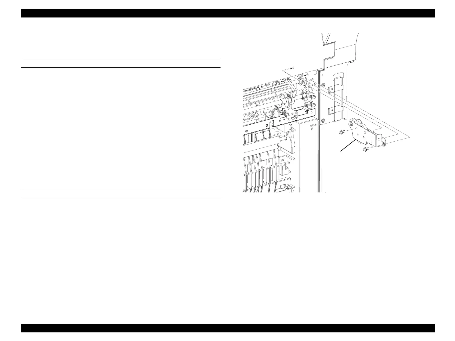
8. Remove the 2 screws (silver, with flange, 6mm) fastening DRIVE ASSY BTR to
the main unit.
9. Remove DRIVE ASSY BTR from the main unit.
REINSTALLATION
1. Match the shaft on DRIVE ASSY BTR with the hole on the main unit, and attach
DRIVE ASSY BTR.
2. Fasten DRIVE ASSY BTR to the main unit with the 2 screws (silver, with flange,
6mm).
3. Attach CHUTE ASSY-FSR and COVER ASSY-RR 2ND. (p366)
4. Attach GUIDE CRU ASSY D. (p388)
5. Attach SENSOR TR-0. (p387)
6. Attach CHASSIS ASSY ESS. (p440)
7. Attach PWBA MCU. (p432)
8. Attach COVER ASSY LH. (p321)
9. Attach 2ND BTR ASSY. (p374)
Figure 4-103. Removal of DRIVE ASSY BTR
Leg_Sec03_098RB
8)
8)
9)
manuals4you.commanuals4you.com
 Loading...


