EPSON AcuLaser CX11/CX11F Revision B
DISASSEMBLY AND ASSEMBLY Printer 321
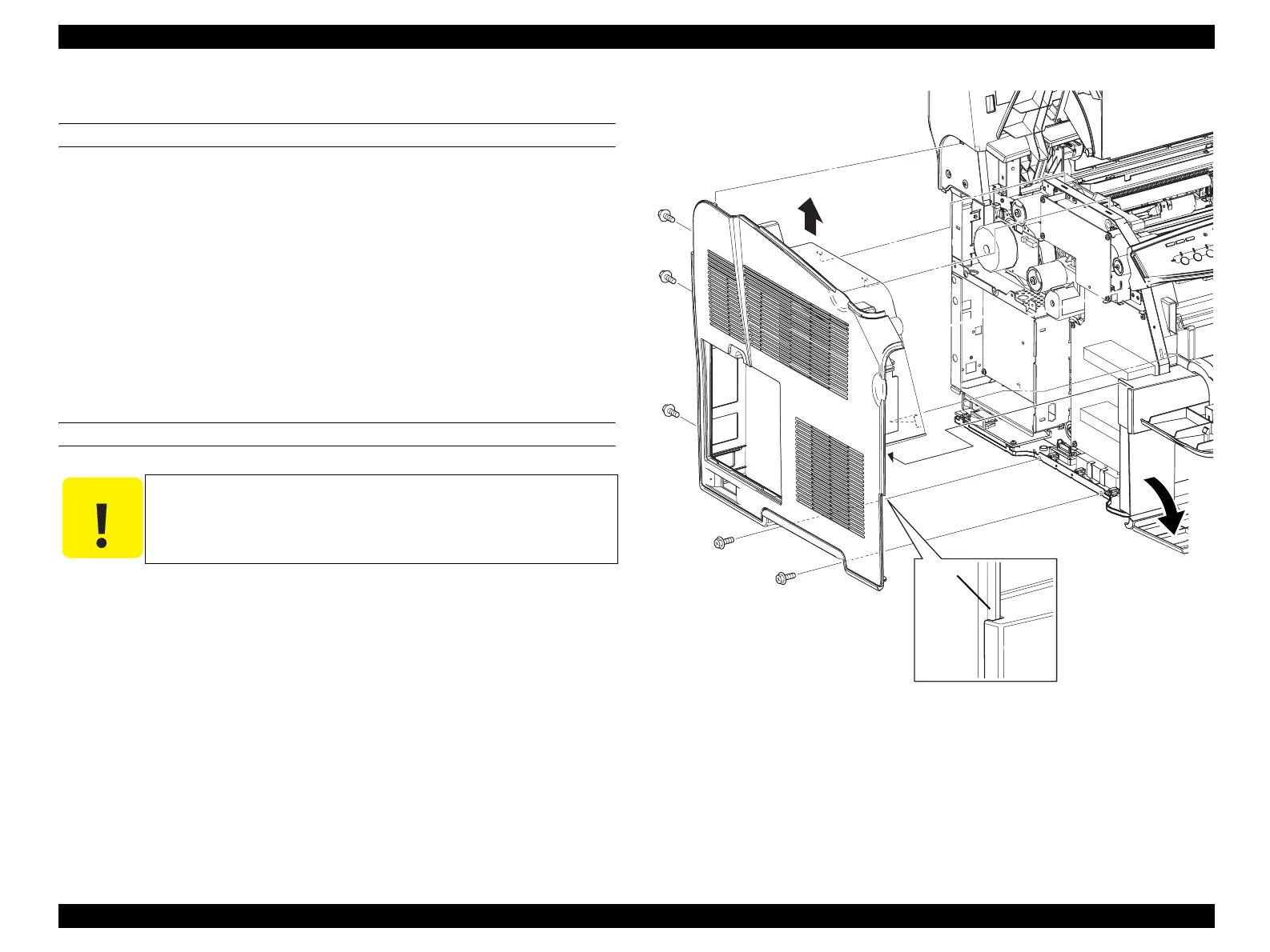
4.2.2.12 COVER ASSY LH
REMOVAL
1. Open COVER ASSY TOP.
2. Open COVER FRONT ASSY U.
3. Open COVER MSI.
4. Remove COVER ESS. (p322)
5. Remove the 5 screws (silver, with flange, 8 mm) fastening the COVER ASSY LH
to the main unit.
6. Lift up the COVER ASSY LH, and unhook the 4 hooks on the rear of the COVER
ASSY LH from the holes on the main unit, and remove the COVER ASSY LH.
REINSTALLATION
1. Match the 4 hooks on the rear side of the COVER ASSY LH with the holes on the
main unit while inserting the protrusion on the front side of the COVER ASSY LH
into the concave portion on the COVER FRONT L, and attach the COVER ASSY
LH.
2. Fasten the COVER ASSY LH to the main unit with the 5 screws (silver, with
flange, 8 mm).
3. Attach COVER ESS. (p322)
4. Close COVER MSI.
5. Close COVER FRONT ASSY U.
6. Close COVER ASSY TOP.
Figure 4-16. Removal of COVER ASSY LH
C A U T I O N
When performing the following work, firmly insert the protrusion
on the front side of the COVER ASSY LH into the indent on the
COVER FRONT L.
Leg_Sec03_011RC
CAUTION
6)
5)
5)
5)
5)
5)
3)
Protrusion
 Loading...


