EPSON AcuLaser CX11/CX11F Revision B
DISASSEMBLY AND ASSEMBLY ADF Section 518
4.4.3.5 EXIT ROLL ASSY
REMOVAL
1. Remove the Scanner. (p306)
2. Remove the ADF Unit. (p481)
3. Remove the ADF COVER R. (p492)
4. Remove the PAPER GUIDE ASSY. (p526)
5. Remove the ADF COVER C. (p496)
6. Remove the ADF BASE ASSY. (p498)
7. Remove the MOTOR. (p509)
8. Remove the GUIDE FRONT ASSY. (p511)
9. Remove the PAPER GUIDE R. (p515)
10. Remove the FRAME COVER ASSY. (p516)
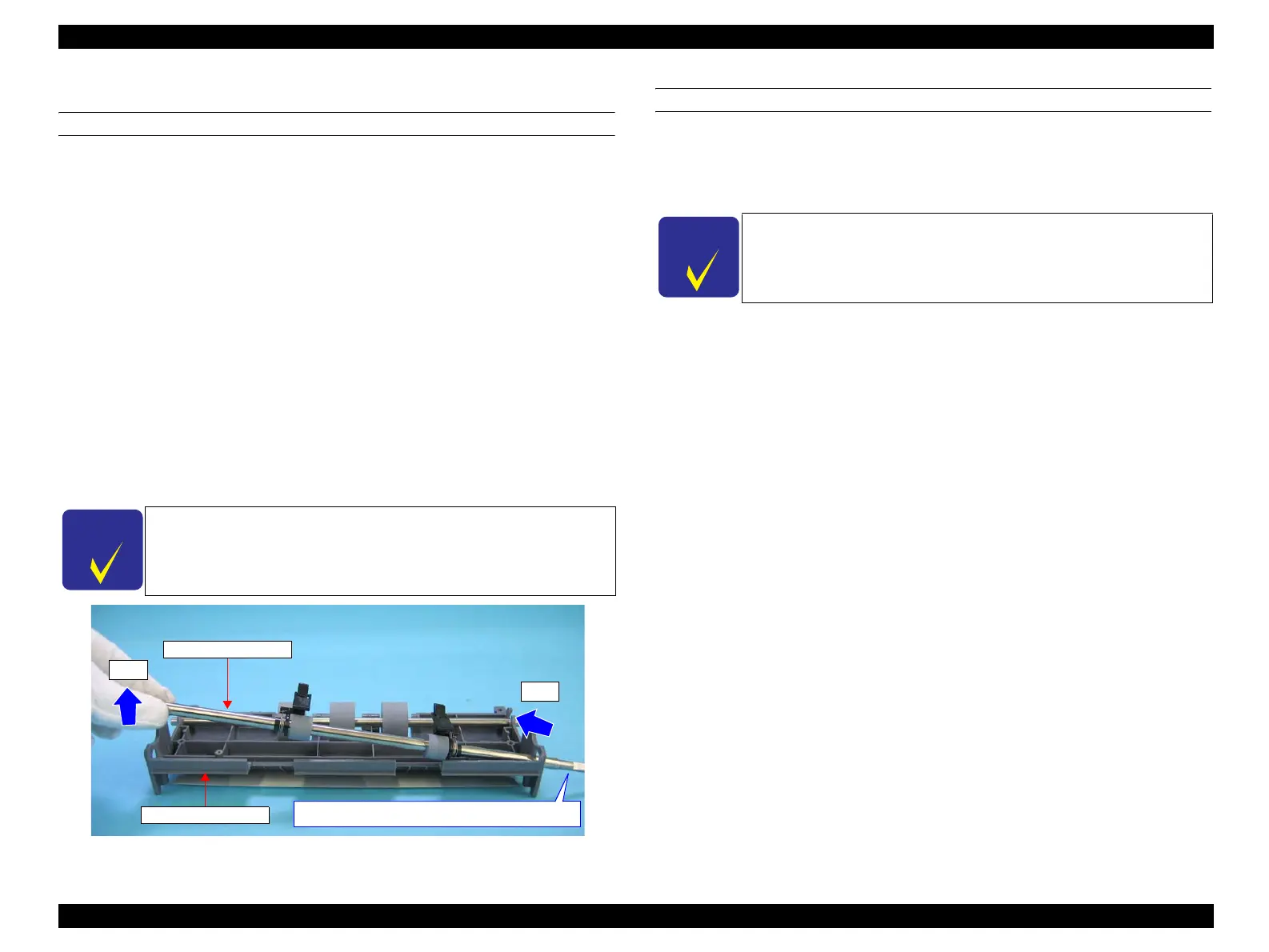
11. Slide the EXIT ROLL ASSY rightward to pull out its left shaft, and then pull out
its right shaft from the ADF FRAME UNIT to remove the EXIT ROLL ASSY.
Figure 4-210. Removal of EXIT ROLL ASSY
REINSTALLATION
1. First insert the one end of the EXIT ROLL ASSY shaft with longer cut surface
into the right shaft hole of the ADF FRAME UNIT, and then insert the other end
into the left shaft hole of the ADF FRAME UNIT.
2. Attach the FRAME COVER ASSY. (p516)
3. Attach the PAPER GUIDE R. (p515)
4. Attach the GUIDE FRONT ASSY. (p511)
5. Attach the MOTOR. (p509)
6. Attach the ADF BASE ASSY. (p498)
7. Attach the ADF COVER C. (p496)
8. Attach the PAPER GUIDE ASSY. (p526)
9. Attach the ADF COVER R. (p492)
10. Attach the ADF Unit. (p481)
11. Install the Scanner. (p306)
C H E C K
P O I N T
When sliding the EXIT ROLL ASSY rightward, lift it upward so
that its roller does not hit the ADF FRAME UNIT.
The cut surface is longer than the other end
11)-2
11)-1
EXIT ROLL ASSY
ADF FRAME UNIT
C H E C K
P O I N T
Make sure to position the EXIT ROLL ASSY with its longer cut
surface side on the right when attaching the EXIT ROLL ASSY to the
ADF FRAME UNIT.
See Figure 4-210.
manuals4you.commanuals4you.com
 Loading...


