EPSON AcuLaser CX11/CX11F Revision B
DISASSEMBLY AND ASSEMBLY ADF Section 517
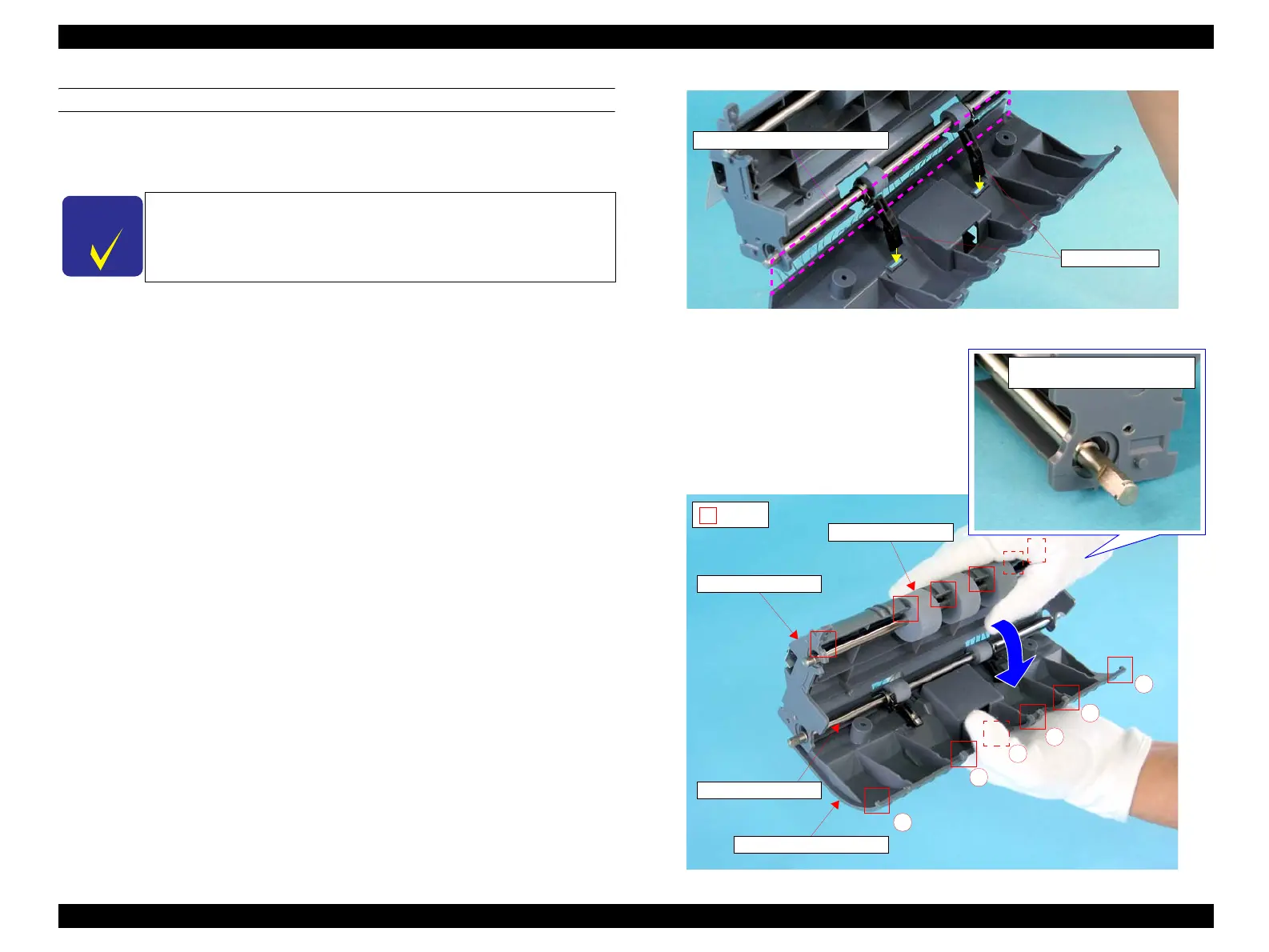
REINSTALLATION
1. Couple the FRAME COVER ASSY (NEUTRALIZING BRUSH attached side) to
the ADF FRAME UNIT positioning them as shown in Figure 4-208.
2. Insert the two STOPPER UPs of the EXIT ROLL ASSY into the holes of the
FRAME COVER ASSY as shown in Figure 4-208.
3. Secure the FRAME COVER ASSY to the ADF FRAME UNIT by inserting six
tabs of the FRAME COVER ASSY in the order shown in Figure 4-209.
4. Secure the FRAME COVER ASSY to the ADF FRAME UNIT with the two
screws (M3 x 8 mm, P-type, A-head). See Figure 4-206.
5. Attach the PAPER GUIDE R. (p515)
6. Attach the GUIDE FRONT ASSY. (p511)
7. Attach the MOTOR. (p509)
8. Attach the ADF BASE ASSY. (p498)
9. Attach the ADF COVER C. (p496)
10. Attach the PAPER GUIDE ASSY. (p526)
11. Attach the ADF COVER R. (p492)
12. Attach the ADF Unit. (p481)
13. Install the Scanner. (p306)
Figure 4-208. Reinstallation of FRAME COVER ASSY (1)
Figure 4-209. Reinstallation of FRAME COVER ASSY (2)
C H E C K
P O I N T
When attaching the TURNING ROLLER to the ADF FRAME
UNIT, make sure to place the shaft of the TURNING ROLLER so
that one end of the shaft with D-shaped cross-section is at the right
side as shown in Figure 4-209.
NEUTRALIZING BRUSH Side
STOPPER UP
2)
D-shaped Cross-section of
TURNING ROLLER Shaft
1
2
3
4
5
6
TURNING ROLLER
ADF FRAME UNIT
EXIT ROLL ASSY
FRAME COVER ASSY
 Loading...


