EPSON AcuLaser CX11/CX11F Revision B
DISASSEMBLY AND ASSEMBLY Printer 467
4.2.12.23 STOPPER CST R
REMOVAL
1. Remove 500 PAPER CASSETTE ASSY. (p442)
2. Remove CHUTE FDR ASSY 500. (p450)
3. Remove COVER RIGHT 500. (p451)
4. Remove COVER LEFT 500. (p449)
5. Remove CLUTCH ASSY FEED. (p457)
6. Remove DRIVE ASSY FEED. (p454)
7. Remove HOUSING ASSY FEED. (p472)
8. Remove CHUTE ASSY 500. (p462)
9. Remove GUIDE CST R. (p468)
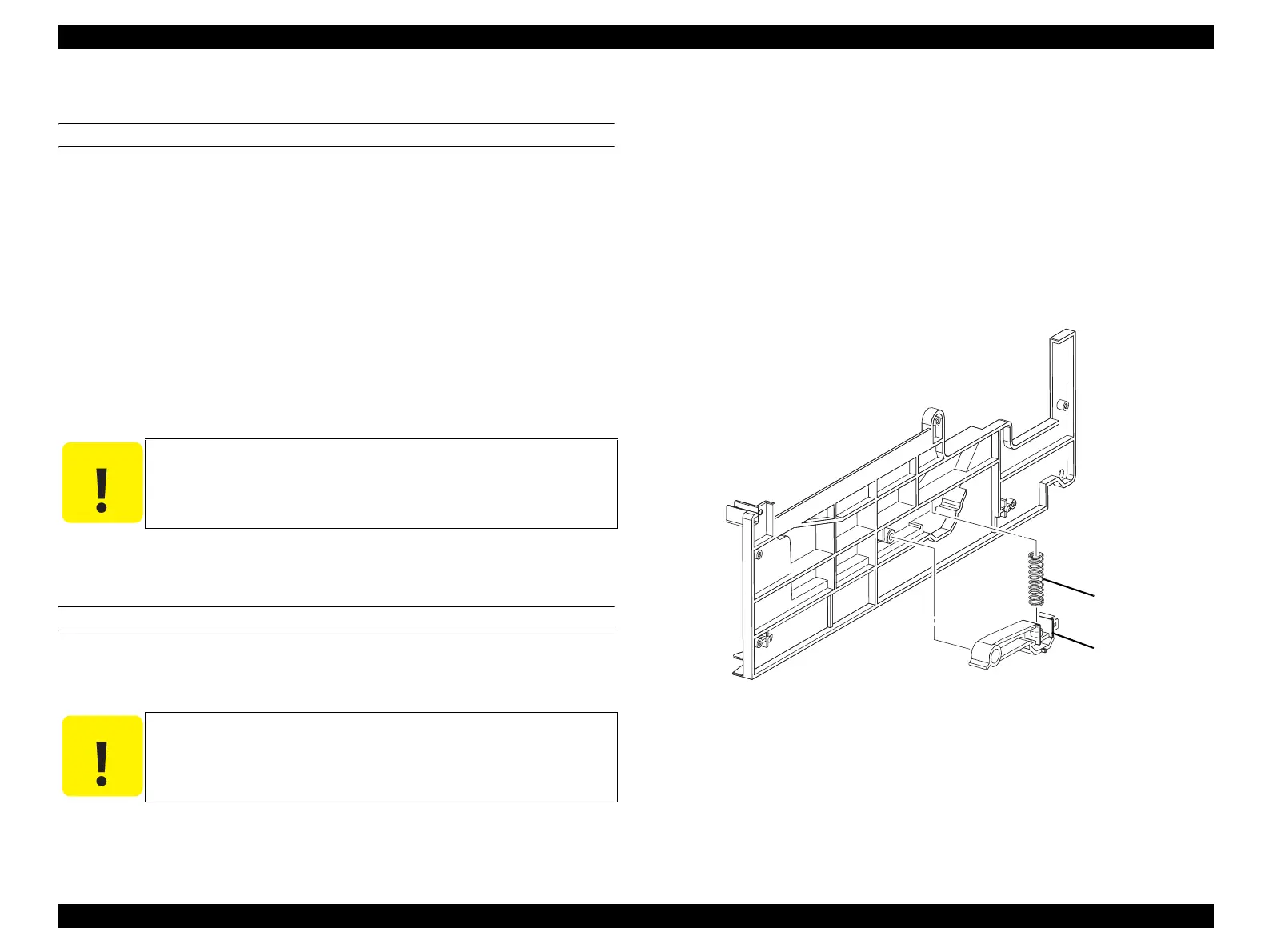
10. Remove STOPPER CST R and SPG LOCK CST LL from GUIDE CST R.
REINSTALLATION
1. Attach SPG LOCK CST LL to the boss on STOPPER CST R, and attach
STOPPER CST R to GUIDE CST R.
2. Attach GUIDE CST R. (p468)
3. Attach CHUTE ASSY 500. (p462)
4. Attach HOUSING ASSY FEED. (p472)
5. Attach DRIVE ASSY FEED. (p454)
6. Attach CLUTCH ASSY FEED. (p457)
7. Attach COVER LEFT 500. (p449)
8. Attach COVER RIGHT 500. (p451)
9. Attach CHUTE FDR ASSY 500. (p450)
10. Attach 500 PAPER CASSETTE ASSY. (p442)
Figure 4-143. Removal of STOPPER CST R
C A U T I O N
When performing the following work, take care not to lose SPG
LOCK CST LL.
C A U T I O N
Make sure that SPG LOCK CST LL is inserted into the boss on
STOPPER CST R and the boss on GUIDE CST R.
Leg_Sec03_181FA
10)-2
10)-1
 Loading...


