EPSON AcuLaser CX11/CX11F Revision B
TROUBLESHOOTING Printer 229
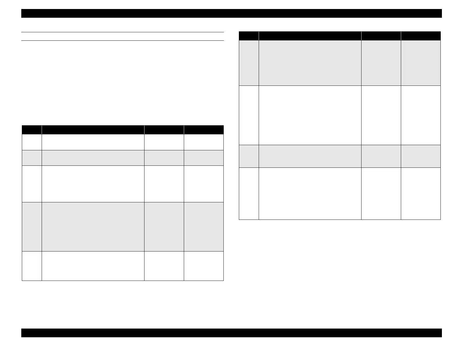
FIP-57
Panel Message
Replace Photocondctr
Possible parts that caused the error
Troubleshooting
Photoconductor Unit SENSOR TNER FULL
HARNESS ASSY MAIN PWBA MCU
LV/HVPS
Step Check Yes No
1
Attachment check of Photoconductor Unit
Is Photoconductor Unit attached correctly?
Go to Step [4]. Re-attach, and go
to step [2].
2
Does the error recur when the power is
turned ON?
Go to Step [3]. End of procedure
3
Check after replacement of Photoconductor
Unit
Replace Photoconductor Unit.
Does the error occur when the power is turned
ON?
Go to Step [4]. End of procedure
4
Operation check of SENSOR TNER FULL
(Toner Full Sensor)
Remove Photoconductor Unit.
The voltage of P413-11 ↔ P413-10 on PWBA
MCU is 0 VDC when the sensor sensing area is
blocked, and is 5 VDC when the sensing area is
not blocked?
Replace PWBA
MCU. (p.432)
Go to Step [5].
5
5 VDC power supply check to SENSOR
TNER FULL
The voltage of P413-12 ↔ P413-10 on PWBA
MCU is 5 VDC?
Go to Step [6]. Go to Step [8].
6
Continuity check of HARNESS ASSY MAIN
Do all of the wiring below have normal
continuity?
J413-10 ↔ J617-3
J413-11 ↔ J617-2
J413-12 ↔ J617-1
Go to Step [7]. Repair broken or
shorted part.
7
Continuity check of HARNESS ASSY TNR
FULL
Disconnect P/J617.
Do all of the wiring below have normal
continuity?
P617-1 ↔ J126-3
P617-2 ↔ J126-2
P617-3 ↔ J126-1
Replace
SENSOR TNER
FULL. (p.400)
Repair broken or
shorted part.
8
5 VDC power supply check to PWBA MCU
The voltage of P410-3 ↔ P410-4 on PWBA
MCU is 5 VDC?
Replace PWBA
MCU. (p.432)
Go to Step [9].
9
Continuity check of HARNESS ASSY MAIN
Disconnect P/J410 from PWBA MCU and P/
J502 from LV/HVPS.
Do all of the wiring below have normal
continuity?
J410-3 ↔ J502-3
J410-4 ↔ J502-4
Replace LV/
HVPS. (p.435)
Repair broken or
shorted part.
Step Check Yes No
 Loading...


