EPSON AcuLaser CX11/CX11F Revision B
DISASSEMBLY AND ASSEMBLY Scanner Section 490
4.3.3.4 FFC CR
REMOVAL
1. Remove the Scanner. (p306)
2. Remove the ADF Unit. (p481)
3. Remove the IR COVER A ASSY. (p482)
4. Remove the CCD MODULE ASSY. (p485)
5. Remove the MOTOR ASSY. (p487)
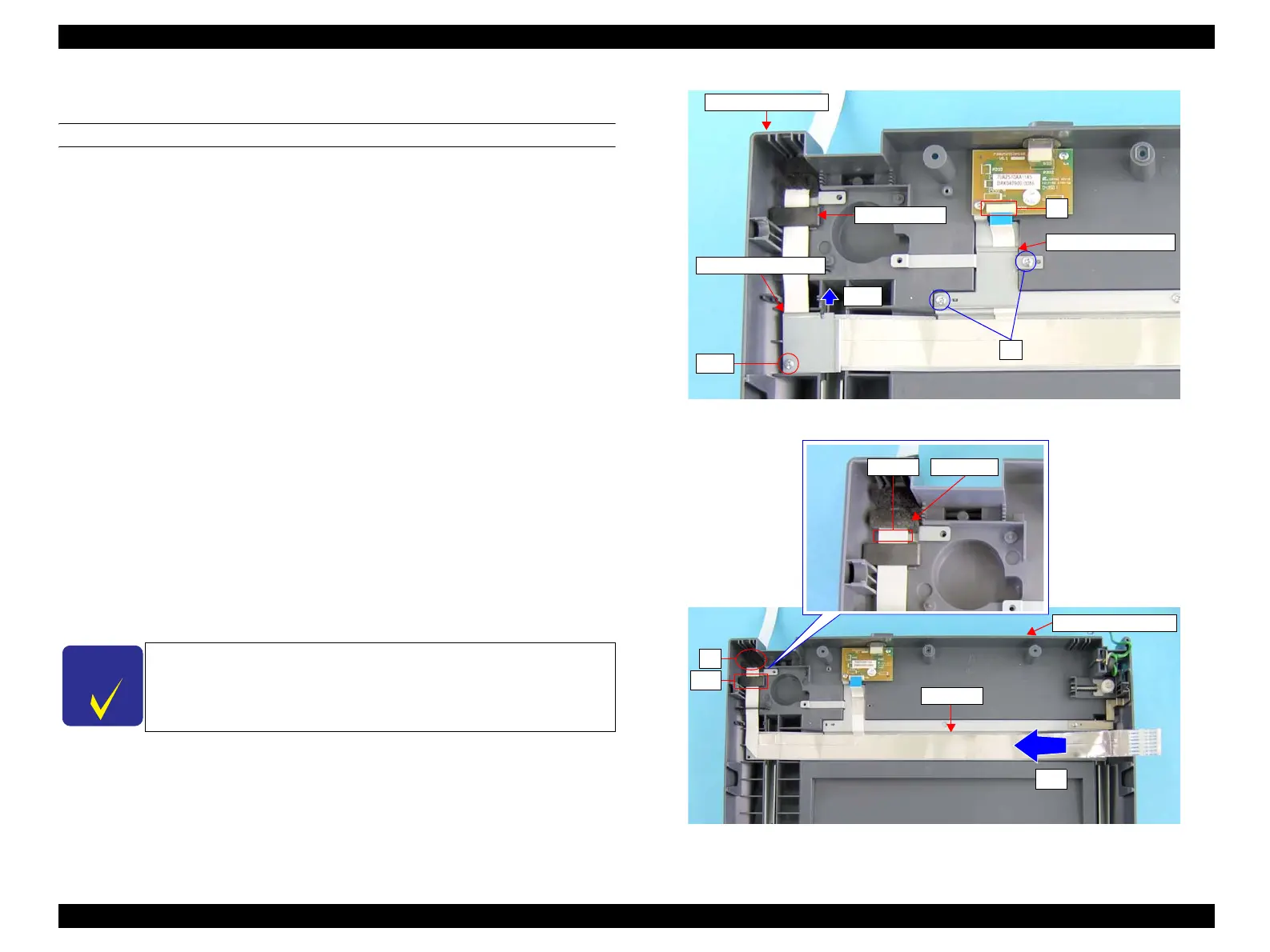
6. Remove the two screws (M3 x 8 mm, P-type, B-head) that secure the PLATE
HARNESS 2 to the IR BASE A ASSY, and remove the PLATE HARNESS 2
from the IR BASE A ASSY.
7. Remove the screw (M3 x 8 mm, P-type, B-head) that secures the PLATE
HARNESS to the IR BASE A ASSY, and slide the PLATE HARNESS in the
direction of an arrow shown in the figure to remove it from the IR BASE A ASSY.
See Figure 4-167.
8. Disconnect the FFC BOARD from the connector on the PCB ASSY.
9. Remove the sponge adhered to the FFC CR, and pull the FFC CR to the inner side
of the IR BASE A ASSY through the hole of the assy.
10. Remove the piece of tape that bundles the FFC CR, and remove the FFC CR from
the ferrite core of the CORE ASSY.
11. Remove the FFC CR from the IR BASE A ASSY.
Figure 4-167. Removal of FFC CR (1)
Figure 4-168. Removal of FFC CR (2)
C H E C K
P O I N T
The FFC CR is secured on the IR BASE A ASSY with two-sided
tapes. Remove the FFC CR slowly and carefully.
Ferrite Core
IR BASE A ASSY
PLATE HARNESS
PLATE HARNESS2
8)
6)
7)-2
7)-1
FFC CR
Tape Sponge
IR BASE A ASSY
11)
10)
9)
manuals4you.commanuals4you.com
 Loading...


