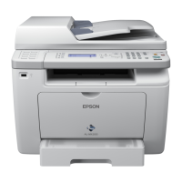
EPSON AcuLaser CX11/CX11F Revision B
TROUBLESHOOTING Printer 200
FIP-34
Panel Message
Jam C
Possible parts that caused the error
Troubleshooting
EXIT SENSOR (Sensor in Fuser) FUSER ASSY
HARNESS ASSY MCU C/L PWBA MCU
LV/HVPS MOT ASSY FSR
Step Check Yes No
1
Check of the paper
Is the paper loaded in the paper tray wrinkled or
torn?
Replace with
new, dry paper.
Go to Step [2].
2
Paper size setting check
Does the size of the paper in use match the size
of the paper set on the control panel?
Go to Step [4]. Change the paper
size setting, and
proceed to step
[3].
3
Does the error recur when a test print is
made?
Go to Step [4]. End of procedure
4
Paper check at Gate section inside FUSER
ASSY
Allow FUSER ASSY to cool down
before performing work.
Remove FUSER ASSY. (p.415)
Is there any paper remaining at the Gate section
inside FUSER ASSY.
Remove the
paper, and go to
[5].
Go to Step [6].
5
Does the error recur when a test print is
made?
Go to Step [6]. End of procedure
6
Shape and operation check of ACTUATOR
in EXIT SENSOR
Does ACTUATOR move smoothly and enter
the sensing area of EXIT SENSOR?
Go to Step [7]. Replace FUSER
ASSY. (p.415)
W A R N I N G
7
Operation check of EXIT SENSOR in
FUSER ASSY
The voltage of P417-8 ↔ P417-7 on PABW
MCU is 0 VDC when ACTUATOR on EXIT
SENSOR is moved and entered the sensing area
of EXIT SENSOR (when there is no paper),
and is 5 VDC when the actuator leaves the
sensing area (when there is paper)?
Go to Step [13]. Go to Step [8].
8
5 VDC power supply check to EXIT
SENSOR in FUSER ASSY
Allow FUSER ASSY to cool down
before performing work.
Remove FUSER ASSY. (p.415)
The voltage of connector J614A-7 ↔ J614A-6
on the printer (connected to FUSER ASSY) is 5
VDC?
Go to Step [9]. Go to step [10]
9
Continuity check of HARNESS ASSY
FUSER SENS and HARNESS ASSY FUSER
in FUSER ASSY
Allow FUSER ASSY to cool down
before performing work.
Remove FUSER ASSY. (p.415)
Disconnect P/J619 and P/J110 in FUSER
ASSY.
Do all of the wiring below have normal
continuity?
P619-1 ↔ J110-3
P619-2 ↔ J110-2
P619-3 ↔ J110-1
J619-3 ↔ P614A-7
J619-2 ↔ P614A-8
J619-1 ↔ P614A-9
Replace EXIT
SENSOR.
Replace FUSER
ASSY. (p.415)
Step Check Yes No
W A R N I N G
W A R N I N G
manuals4you.commanuals4you.com

 Loading...


