EPSON AcuLaser CX11/CX11F Revision B
DISASSEMBLY AND ASSEMBLY Printer 314
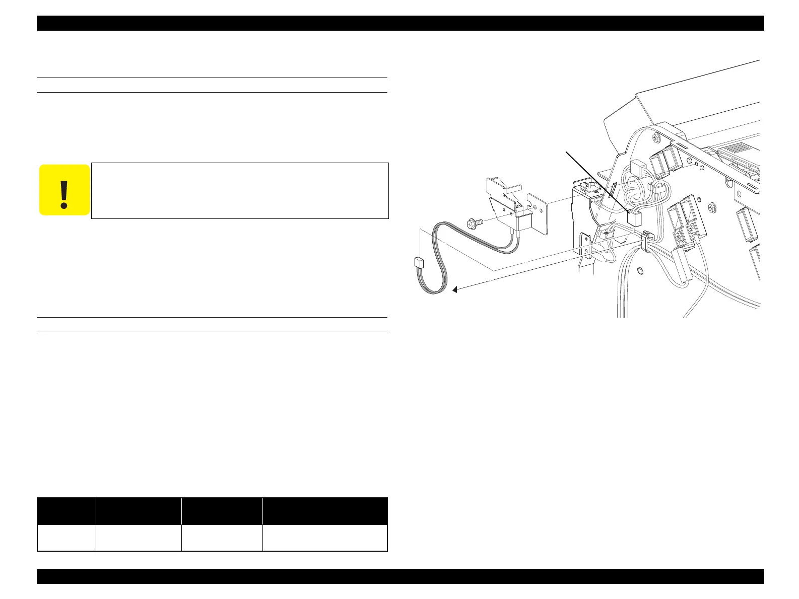
4.2.2.6 SWITCH ASSY TOP
REMOVAL
1. Remove COVER ASSY RH. (p326)
2. Unclamp the two clamps fastening the harness of SWITCH ASSY TOP, and
remove the harness.
3. Disconnect connector (P/J116, blue) of SWITCH ASSY TOP.
4. Remove the screw (silver, with flange, 8 mm) fastening SWITCH ASSY TOP to
the main unit.
5. Remove SWITCH ASSY TOP from the main unit.
REINSTALLATION
1. Match the hole on SWITCH ASSY TOP with the boss on the main unit, and
attach.
2. Fasten SWITCH ASSY TOP to the main unit with the screw (silver, with flange, 8
mm).
3. Connect connector (P/J116, blue) of SWITCH ASSY TOP.
4. Clamp the harness of SWITCH ASSY TOP with the two clamps.
5. Attach COVER ASSY RH. (p326)
Figure 4-9. Removal of SWITCH ASSY TOP
C A U T I O N
When performing the following work, leave the intermediate
connector (blue) on the harness side.
Table 4-3. Symptoms when the connector is loose
Connector No. Panel Indication Symptom
Error Caused by Connector
Disconnection
P/J116 B Open
Printing is not
possible.
---
Leg_03_006EC
Intermediate
connector (Blue)
4)
2)
3)
(Blue)
manuals4you.commanuals4you.com
 Loading...


