EPSON AcuLaser CX11/CX11F Revision B
DISASSEMBLY AND ASSEMBLY Printer 437
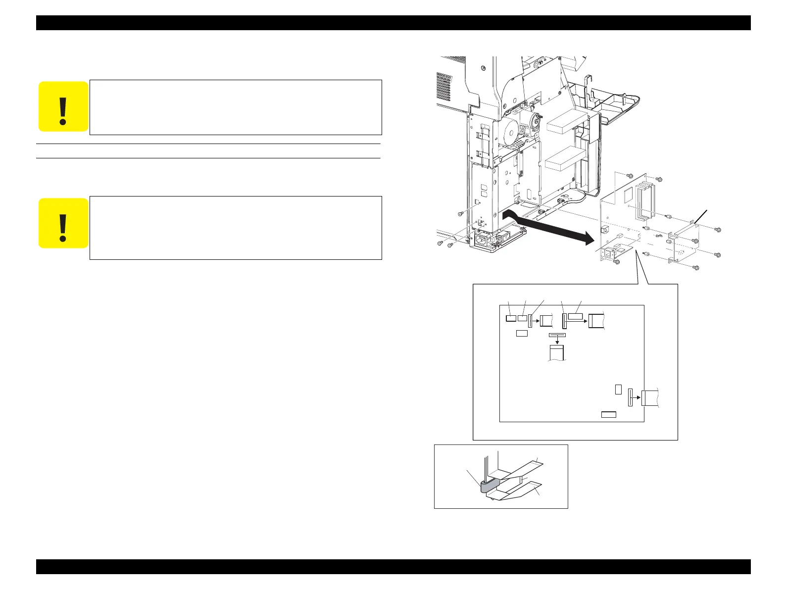
4.2.11.7 PWBA ESS (BOARD ASSY., MAIN)
REMOVAL
1. Remove COVER ASSY LH. (p321)
2. Remove the four screws (silver, with flange, 6 mm) that secure the PWBA FAX to
the PWBA ESS.
3. Disconnect the connector from the PWBA ESS and remove the PWBA FAX.
4. Remove the four SPACERs on the PWBA ESS.
5. Disconnect the all connectors on the PWBA ESS.
6. Remove the four screws (silver, with flange, 6 mm) that secure the PWBA ESS to
the CHASSIS ESS, and remove the three screws that secure the connectors for the
interface.
7. Remove the PWBA ESS taking out the interface connector from the hole on the
CHASSIS ESS.
Figure 4-116. Removal of PWBA ESS
C A U T I O N
Avoid staticky places such as on a carpet especially when removing
or inserting a Board. Before starting work with the Board, make
sure to touch metallic portion of the printer connected to the earth
to let your body come out free of static electricity.
C A U T I O N
The following Step 2 to 4 are for the AcuLaser CX11F (fax model).
The AcuLaser CX11 (base model) does not have PWBA FAX, and
four screws (silver, with flange, 6 mm) are attached instead of the
four SPACERs. Remove the four screws when disassembling the
base model.
Leg_03_109RC
CN705 CN502
CN602
CN501
CN601
CN704
CN703
CN701
CN702 CN405
CN410
FERRITE CORE
CN704(12 pin)
CN701(14 pin)
CN702(13 pin)
CAUTION
6)
6)
6)
6)
6)
4)
4)
6)
2)
2)
2)
4)
6)
7)
5)
3)
2)4)
 Loading...


