EPSON AcuLaser CX11/CX11F Revision B
APPENDIX Printer System Electrical Connection 573
7.2.3 Wiring Connection Diagram between Parts
7.2.3.1 Symbols used in the Wiring Connection Diagram between
Parts
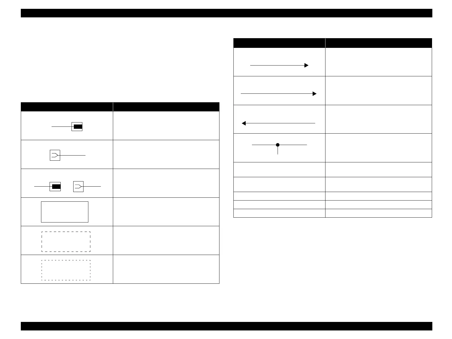
The table below shows how to interpret the Wiring Connection Diagram between Parts
given on the following pages.
Commonly used symbols are omitted here.
Table 7-4. List of the Symbols
Symbol Explanation
Indicates a plug.
Indicates a jack.
Indicates a Pin YY or Jack YY of the connector P
XX and J XX.
Indicates a part.
Indicates a functional component in a part, and its
name.
Indicates control inside the PWB, and a brief
outline of the control.
P/JXX
YY
PWBA HNB DRV PL
X.Y.Z
Heater
Control
Indicates a connection between parts with a
harness or wire, and its signal name/details.An
arrow indicates the direction of the signal.
Indicates the logical value (Low: L, High: H) of
the signal for enabling the function. The voltage is
the value when the signal is High.An arrow
indicates the direction of the signal.
Indicates the logical value (Low: L, High: H) of
the signal when the function is detected. The
voltage is the value when the signal is High. An
arrow indicates the direction of the signal.
Indicates cable-to-cable connection.
I/L +24VDC
Indicates the DC voltage when the HNB MCU
WITH CPU internal interlock switch is ON.
+5VDC
+3.3VDC
Indicates DC voltage.
SG
Indicates a Signal Ground.
AG
Indicates Analog Ground.
RTN
Indicates a Return.
Table 7-4. List of the Symbols
Symbol Explanation
DEVE_A
REGI CLUTCH ON (L) +24VDC
EXIT PAPER SENSED (L) +3.3VDC
 Loading...


