EPSON AcuLaser CX11/CX11F Revision B
DISASSEMBLY AND ASSEMBLY Printer 388
4.2.6.2 GUIDE CRU ASSY D
REMOVAL
1. Remove 2ND BTR ASSY. (p374)
2. Remove COVER ASSY LH. (p321)
3. Remove PWBA MCU. (p432)
4. Remove CHASSIS ASSY ESS. (p440)
5. Remove CHUTE ASSY-FSR and COVER ASSY-RR 2ND. (p366)
6. Remove FUSER LOCK SWITCH. (p417)
7. Remove SENSOR TR-0. (p387)
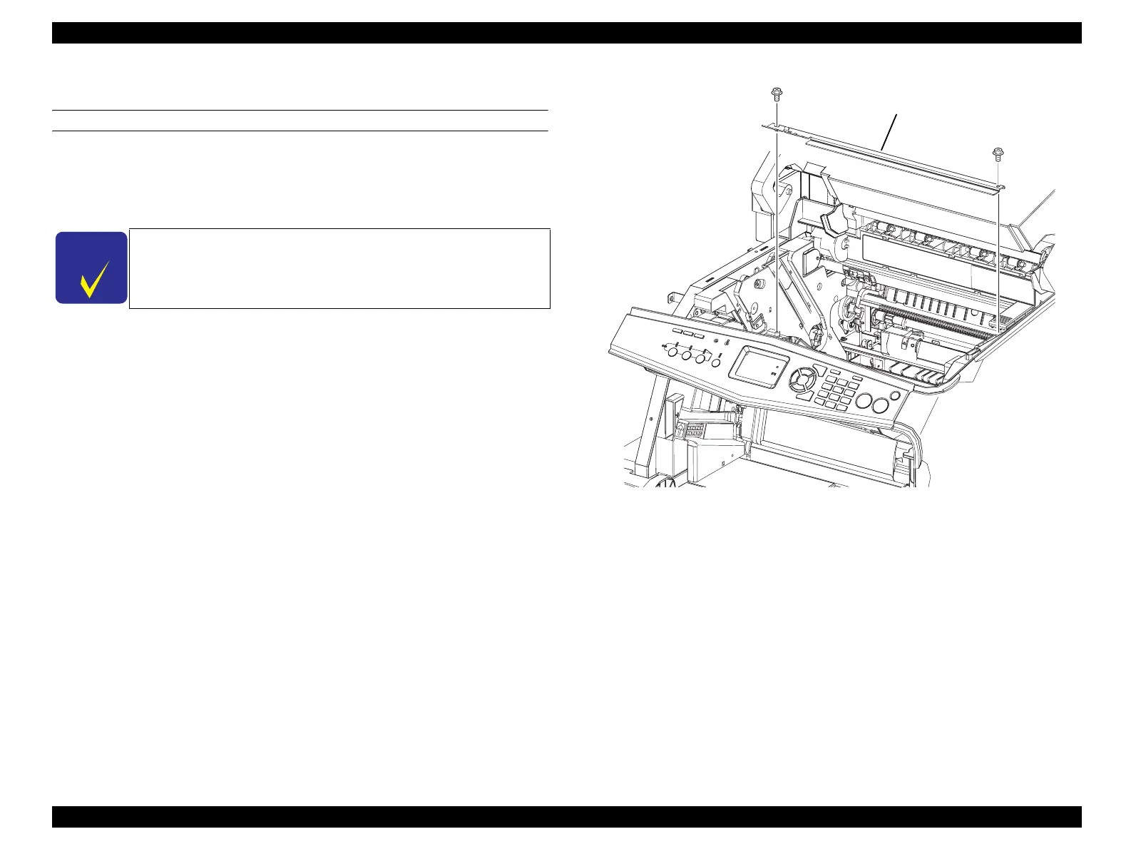
8. Remove the 2 screws (silver, with flange, tapping, 6 mm) fastening PLATE-TR-0
to GUIDE CRU ASSY D and GUIDE CRU ASSY AD.
9. Remove PLATE-TR-0 from GUIDE CRU ASSY D and GUIDE CRU ASSY AD.
Figure 4-74. Removal of GUIDE CRU ASSY D (1)
C H E C K
P O I N T
When performing the following work, connectors need not be
disconnected from PWBA ESS.
Leg_Sec03_077RA
6)
6)
7)
manuals4you.commanuals4you.com
 Loading...


