EPSON AcuLaser CX11/CX11F Revision B
DISASSEMBLY AND ASSEMBLY ADF Section 525
4.4.4 ADF PCB ASSY
4.4.4.1 ADF PCB ASSY
REMOVAL
1. Remove the Scanner. (p306)
2. Remove the ADF Unit. (p481)
3. Remove the ADF COVER R. (p492)
4. Remove the PCB COVER. (p495)
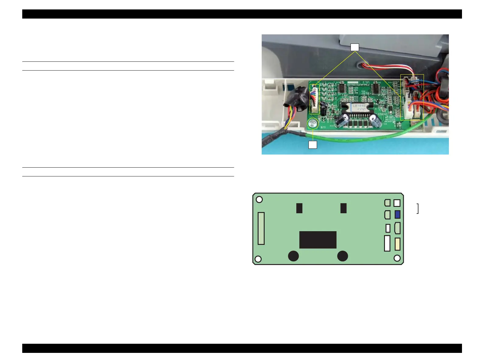
5. Disconnect the nine connectors on the ADF PCB ASSY.
6. Remove the screw (M3 x 8 mm, P-type, A-head) that secures the ADF PCB ASSY
to the SDH COVER, and remove the ADF PCB ASSY.
REINSTALLATION
1. Secure the ADF PCB ASSY to the SDH COVER with the screw (M3 x 8 mm, P-
type, A-head).
2. Connect the all harnesses to the nine connectors on the ADF PCB ASSY. See
Figure 4-218.
3. Attach the PCB COVER. (p495)
4. Attach the ADF COVER R. (p492)
5. Attach the ADF Unit. (p481)
6. Install the Scanner. (p306)
Figure 4-217. Removal of ADF PCB ASSY
Figure 4-218. Connector Layout
5)
6)
P301
CABLE
P303
MOTOR
PAPER GUIDE
ASSY
P306
AS SENSOR
P309
P308
P305
COVER SENSOR
P307
MAGNETIC CLUTCH
P301
CONNECTOR UNIT ACEMU
(ADF FRAME ASSY)
P302
CONNECTOR UNIT ACEMU
(ADF BASE)
 Loading...


