EPSON AcuLaser CX11/CX11F Revision B
DISASSEMBLY AND ASSEMBLY Scanner Section 485
4.3.3 IR A Assy
4.3.3.1 CCD MODULE ASSY
REMOVAL
1. Remove the Scanner. (p306)
2. Remove the ADF Unit. (p481)
3. Remove the IR COVER A ASSY. (p482)
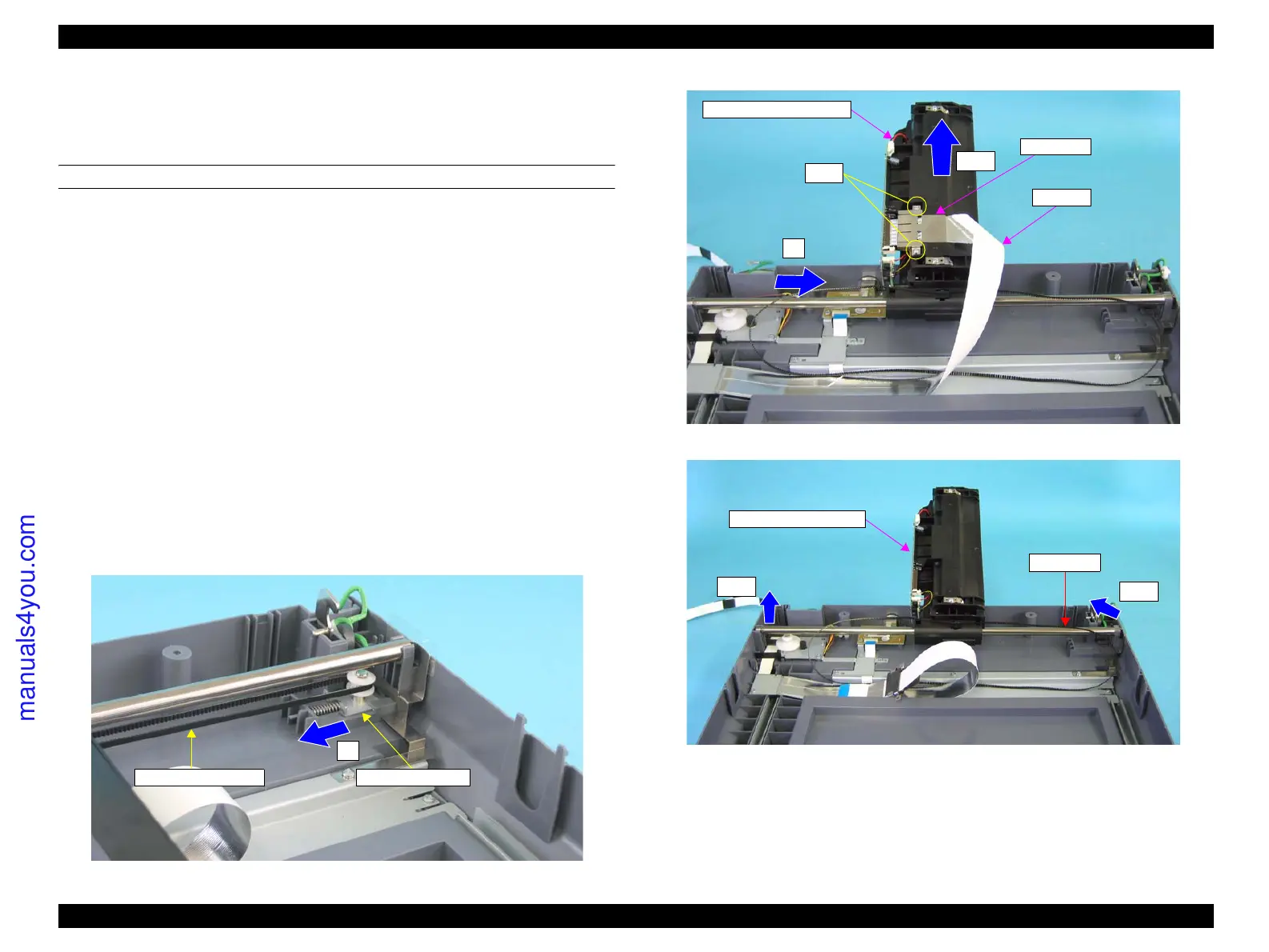
4. Slide the PULLEY ASSY in the direction of an arrow shown in Figure 4-161 to
release the tension of the IR TIMING BELT, and remove the IR TIMING BELT
from the pulley of the PULLEY ASSY.
5. Move the CCD MODULE ASSY to the center.
6. Turn the CCD MODULE ASSY upward upon the IR SHAFT, and hold it to
remove the two screws (M3 x 6 mm, B-type, P-head) that secure the FFC CR to
the CCD MODULE ASSY.
7. Disconnect the FFC CR from the connector on the CCD MODULE ASSY.
8. Release the left end of the IR SHAFT from the bearing of the IR BASE ASSY, and
remove the CCD MODULE ASSY together with the IR SHAFT.
9. Pull out the IR SHAFT from the CCD MODULE ASSY.
Figure 4-161. Releasing the Tension of IR TIMING BELT
Figure 4-162. Removal of FFC CLIP
Figure 4-163. Removal of CCD MODULE ASSY
PULLEY ASSY
4)
IR TIMING BELT
FFC CLIP
FFC CR
5)
6)-2
6)-1
CCD MODULE ASSY
IR SHAFT
CCD MODULE ASSY
8)-2
8)-1
manuals4you.com
 Loading...


