EPSON AcuLaser CX11/CX11F Revision B
DISASSEMBLY AND ASSEMBLY ADF Section 512
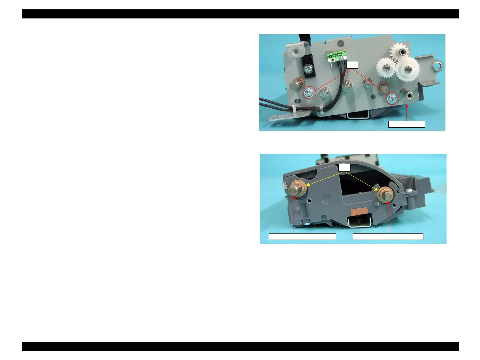
11. Remove the two screws (M3 x 8 mm, P-type, A-head) that secure the FIX PLATE
R to the ADF FRAME UNIT, and remove the FIX PLATE R from the ADF
FRAME UNIT.
12. Remove BUSH D6 from the shaft of the TURNING ROLLER and the shaft of the
EXIT ROLL ASSY respectively.
Figure 4-200. Removal of GUIDE FRONT ASSY (3)
Figure 4-201. Removal of GUIDE FRONT ASSY (4)
11)
FIX PLATE R
12)
Shaft of EXIT ROLL ASSY Shaft of TURNING ROLLER
manuals4you.commanuals4you.com
 Loading...


