EPSON AcuLaser CX11/CX11F Revision B
DISASSEMBLY AND ASSEMBLY Printer 372
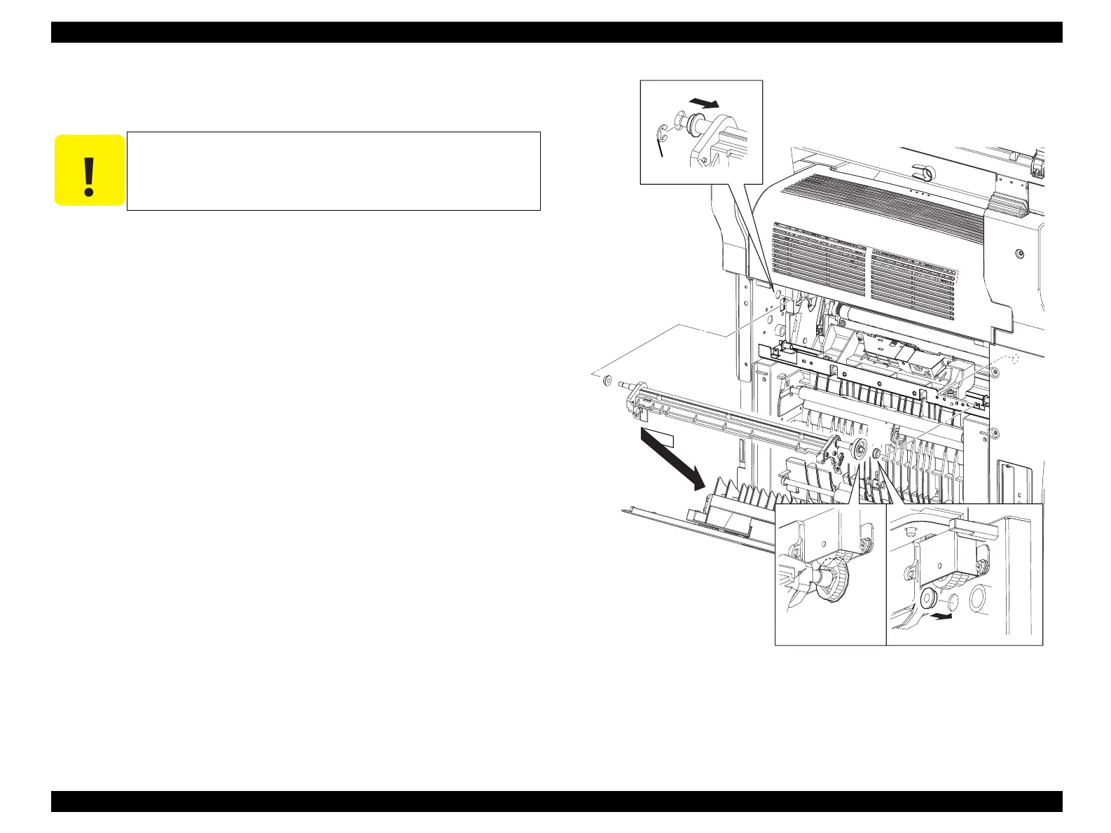
7. Remove the E-ring fastening the right-side shaft on FRAME ASSY-2ND to the
main unit, and slide BEARING-BRUSH CAM to the left.
8. Temporarily slide FRAME ASSY-2ND to the right, and draw out the shaft on
FRAME ASSY-2ND from the left-side bearing on the main unit, and remove
FRAME ASSY-2ND together with BEARING-BRUSH CAM.
9. Remove BEARING-BRUSH CAM from FRAME ASSY-2ND.
Figure 4-63. Removal of FRAME ASSY-2ND (2)
C A U T I O N
When performing the following work, take care not to drop or lose
BEARING-BRUSH CAM.
Leg_Sec03_147RB
7)-2
7)-1
9)
8)
[3)]
[1)]
9)
manuals4you.commanuals4you.com
 Loading...


