EPSON AcuLaser CX11/CX11F Revision B
DISASSEMBLY AND ASSEMBLY Printer 392
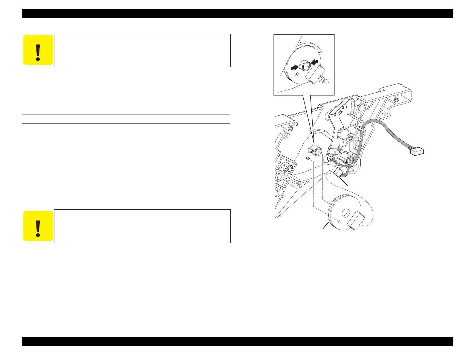
9. Unhook the hook fastening ANTENNA ASSY to GUIDE CRU ASSY D, and
remove ANTENNA ASSY.
10. Disconnect connector (P/J109) from ANTENNA ASSY.
REINSTALLATION
1. Connect connector (P/J109) to ANTENNA ASSY.
2. Match the boss on GUIDE CRU ASSY D with the hole on ANTENNA ASSY,
attach ANTENNA ASSY, and fasten with a hook.
3. Attach SPRING-TORSION ARM to ARM-COUPLING, and insert the shaft on
LINK-COUPLING into the long oblong hole on ARM-COUPLING.
4. Turn ARM-COUPLING 90°, attach ARM-COUPLING to the shaft on GUIDE
CRU ASSY D, fasten with a hook, and hook SPRING-TORSION ARM onto the
notch of GUIDE CRU ASSY D.
5. Attach GUIDE CRU ASSY D. (p388)
6. Attach SENSOR TR-0. (p387)
7. Attach CHASSIS ASSY ESS. (p440)
8. Attach PWBA MCU. (p432)
9. Attach COVER ASSY LH. (p321)
10. Attach 2ND BTR ASSY. (p374)
Figure 4-78. Removal of ANTENNA ASSY (2)
C A U T I O N
When unhooking the hook fastening ANTENNA ASSY, take care
not to damage the hook.
C A U T I O N
SPRING-TORSION ARM must be firmly hooked onto the shaft of
ARM-COUPLING and LATCH ASSY D.
Leg_Sec03_080FA
10)
9)-1
9)-2
manuals4you.commanuals4you.com
 Loading...


