EPSON AcuLaser CX11/CX11F Revision B
DISASSEMBLY AND ASSEMBLY Printer 409
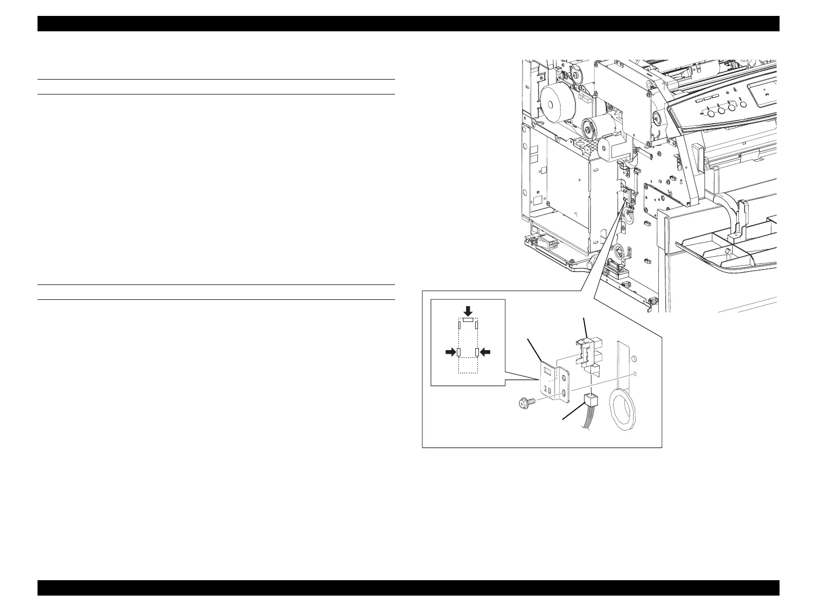
4.2.8.5 SENSOR ROTARY HOME POSI
REMOVAL
1. Remove COVER ASSY LH. (p321)
2. Remove LV/HVPS. (p435)
3. Remove the screw (silver, with flange, 6 mm) fastening BRACKET SENSOR to
the main unit.
4. Remove BRACKET SENSOR from the main unit together with SENSOR
ROTARY HOME POSI.
5. Disconnect connector (P/J105) from SENSOR ROTARY HOME POSI.
6. Unhook the three hooks fastening SENSOR ROTARY HOME POSI to
BRACKET SENSOR, and remove SENSOR ROTARY HOME POSI.
REINSTALLATION
1. Match the hooks on SENSOR ROTARY HOME POSI with the attachment
position, and attach to BRACKET SENSOR.
2. Connect connector (P/J105) to SENSOR ROTARY HOME POSI.
3. Match the hole on BRACKET SENSOR with the boss on the main unit, and attach
BRACKET SENSOR together with SENSOR ROTARY HOME POSI.
4. Fasten BRACKET SENSOR to the main unit with the screw (silver, with flange, 6
mm).
5. Attach LV/HVPS. (p435)
6. Attach COVER ASSY LH. (p321)
Figure 4-94. Removal of SENSOR ROTARY HOME POSI
Leg_Sec03_093RA
6)-1
6)-2
4)
3)
5)
 Loading...


