EPSON AcuLaser CX11/CX11F Revision B
DISASSEMBLY AND ASSEMBLY Printer 423
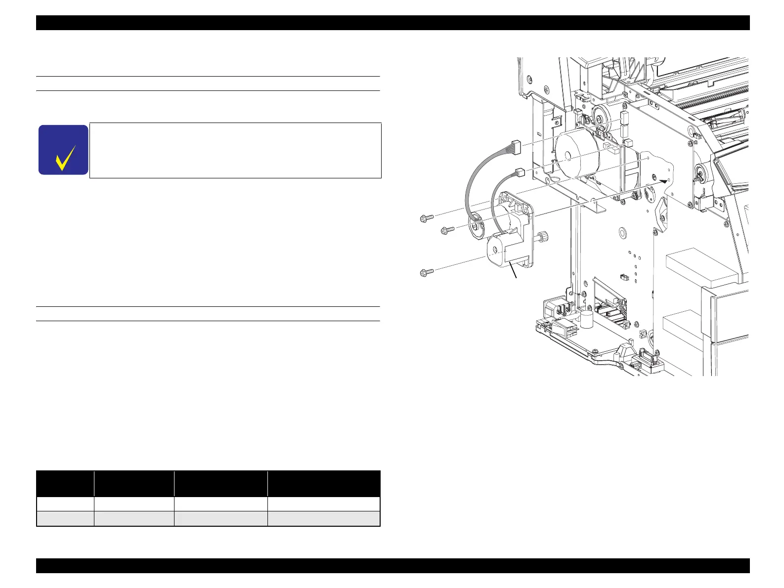
4.2.10.4 MOT ASSY MAG
REMOVAL
1. Remove COVER ASSY LH. (p321)
2. Remove CHASSIS ASSY ESS. (p440)
3. Disconnect connector (P/J405) and connector (P/J406) from PWBA MCU.
4. Remove the 3 screws (silver, with flange, 10 mm) fastening MOT ASSY MAG to
the main unit.
5. Remove MOT ASSY MAG from the main unit.
REINSTALLATION
1. Match the boss on MOT ASSY MAG with the hole on the main unit, and attach.
2. Fasten MOT ASSY MAG to the main unit with the 3 screws (silver, with flange,
10 mm).
3. Connect connector (P/J405) and connector (P/J406) to PWBA MCU.
4. Attach CHASSIS ASSY ESS. (p440)
5. Attach COVER ASSY LH. (p321)
Figure 4-106. Removal of MOT ASSY MAG
C H E C K
P O I N T
When performing the following work, the connector of PWBA ESS
does not need to be removed.
Table 4-9. Symptoms when the connector is loose
Connector
No.
Panel Indication Symptom
Error Caused by Connector
Disconnection
P/J405 Ready Entirely Faint
FIP-P17
P/J406 Ready Normal printing
---
Leg_Sec03_102RA
3)
3)
4)
4)
4)
5)
justmanuals.com
 Loading...


