EPSON AcuLaser CX11/CX11F Revision B
TROUBLESHOOTING Printer 179
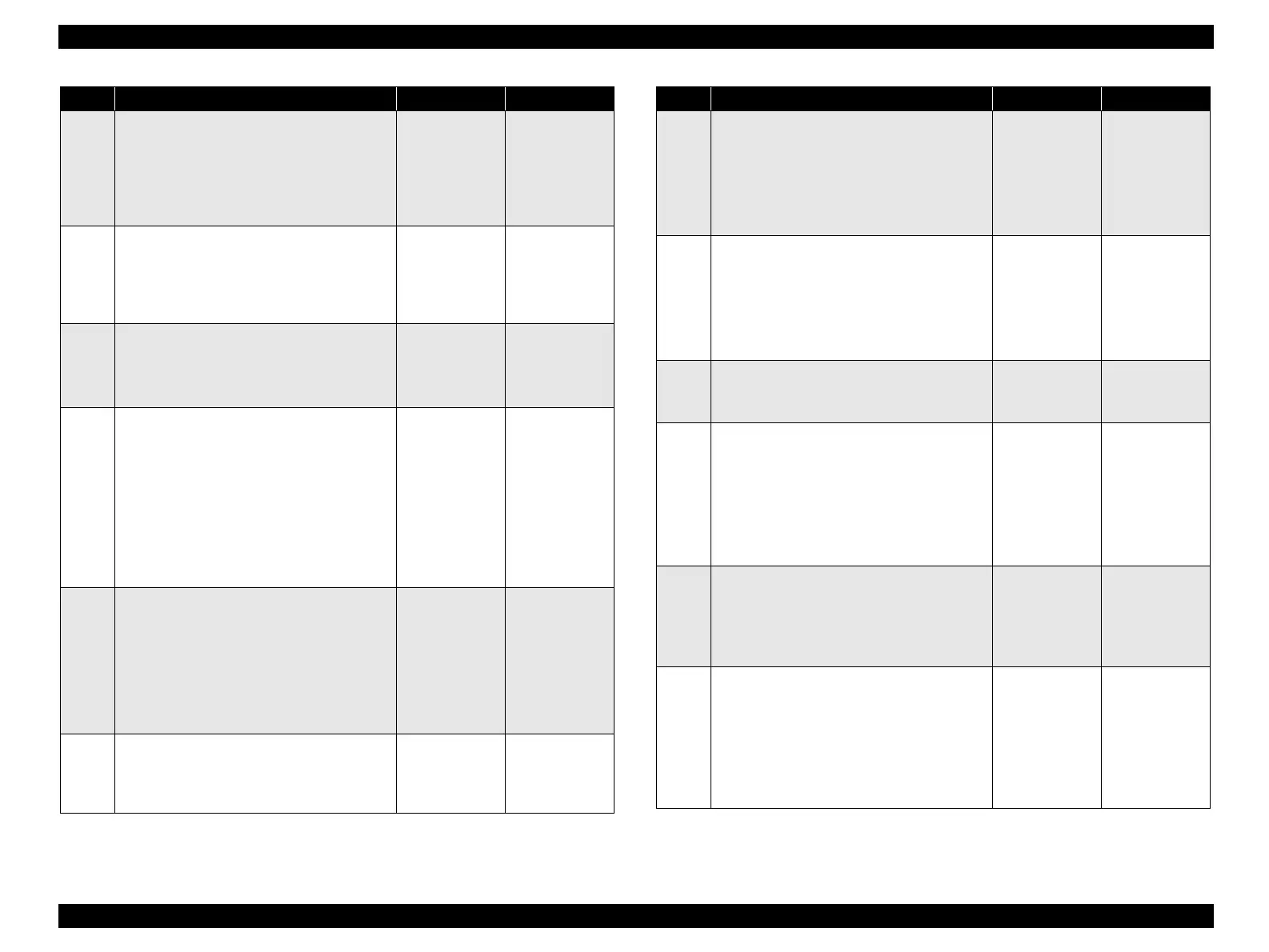
12
Operation check of ACTUATOR T/R
Does ACTUATOR T/R move smoothly
without any damage? Does it leave the sensing
area of Tray Path Sensor when there is paper?
Does it enter the sensing area when there is no
paper?
Go to Step [13].
Replace
ACTUATOR
T/R.
(p.477)
13
Operation check of SENSOR T/R
The voltage of P437-15 ↔ P437-14 on PWBA
TRAY CONT is 0 VDC when ACTUATOR T/
R enters the sensing area of SENSOR T/R, and
is 5 VDC when it leaves the sensing area?
Go to Step [22]. Go to Step [14].
14
5 VDC power supply check to SENSOR T/R
Remove COVER LEFT 500.
The voltage of P437-13 ↔ P437-14 on PWBA
TRAY 500 is 5 VDC?
Go to Step [15]. Go to Step [17].
15
Continuity check of HARNESS-ASSY FEED
MAIN
Disconnect P/J437 and P/J618 from PWBA
TRAY CONT.
Do all of the wiring below have normal
continuity?
J437-13 ↔ J618-3
J437-14 ↔ J618-2
J437-15 ↔ J618-1
Go to Step [16]. Replace
HARNESS-
ASSY FEED
MAIN.
16
Continuity check of HARNESS ASSY FEED 3
Disconnect P/J618.
Do all of the wiring below have normal
continuity?
P618-4 ↔ J120-3
P618-5 ↔ J120-2
P618-6 ↔ J120-1
Replace
SENSOR
T/R. (p.478)
Repair broken or
shorted part.
17
5 VDC power supply check to PWBA TRAY
500
The voltage of P435-6 ↔ P435-5 on PWBA
TRAY 500 is 5 VDC?
Go to Step [9]. Go to Step [18].
Step Check Yes No
18
Continuity check of HARNESS-ASSY FEED 1
Disconnect P/J435 from PWBA TRAY CONT.
Do all of the wiring below have normal
continuity?
J435-6 ↔ P608-5
J435-5 ↔ P608-6
Go to Step[19]. Replace
HARNESS-
ASSY FEED 1.
(p.458)
19
Continuity check of HARNESS ASSY MAIN
Disconnect P/J421 from PWBA MCU.
Do all of the wiring below have normal
continuity?
J421-5 ↔ J608-6
J421-6 ↔ J608-5
Go to Step [20]. Repair broken or
shorted part.
20
5 VDC power supply check to PWBA MCU
The voltage of P410-3 ↔ P410-4 on PWBA
MCU is 5 VDC?
Replace PWBA
MCU. (p.432)
Go to Step [21].
21
Continuity check of HARNESS ASSY MAIN
Disconnect P/J410 from PWBA MCU and P/
J502 from LV/HVPS.
Do all of the wiring below have normal
continuity?
J410-3 ↔ J502-3
J410-4 ↔ J502-4
Replace LV/
HVPS. (p.435)
Repair broken or
shorted part.
22
Operation check of CLUTCH ASSY FEED
Does CLUTCH ASSY FEED operate
normally?
Make a test print and confirm by the operating
noise.
Go to Step [30]. Go to Step [23].
23
Continuity check of HARNESS-ASSY FEED
MAIN
Disconnect P/J437 from PWBA TRAY CONT.
Do all of the wiring below have normal
continuity?
J437-6 ↔ P609-2
J437-7 ↔ P609-1
Go to Step [24]. Replace
HARNESS-
ASSY FEED
MAIN.
Step Check Yes No
 Loading...


