EPSON AcuLaser CX11/CX11F Revision B
TROUBLESHOOTING Printer 184
11
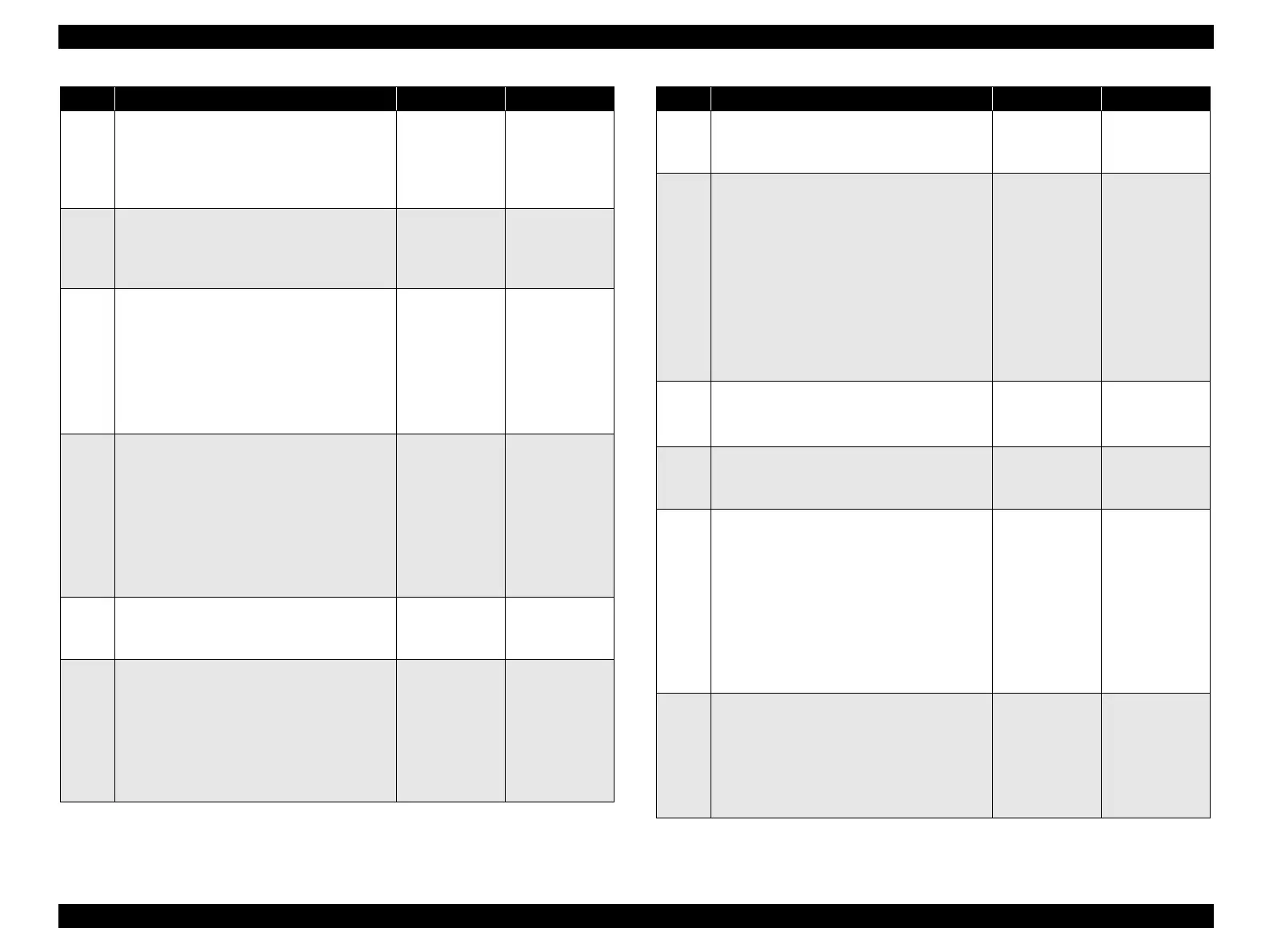
Operation check of SENSOR REGI
The voltage of P408-12 ↔ P408-11 on PWBA
MCU is 0 VDC when ACTUATOR REGI
enters the sensor sensing area, and is 5 VDC
when it leaves the sensing area?
Go to Step [17]. Go to Step [12].
12
5 VDC power supply check to SENSOR
REGI
The voltage of P408-10 ↔ P408-11 on PWBA
MCU is 5 VDC?
Go to Step [13]. Go to Step [15].
13
Continuity check of HARNESS-ASSY P/H1
Disconnect the P/J408 from PWBA MCU.
Do all of the wiring below have normal
continuity?
J408-10 ↔ J603-3
J408-11 ↔ J603-2
J408-12 ↔ J603-1
Go to Step [14]. Replace
HARNESS-
ASSY P/H1.
14
Continuity check of HARNESS-ASSY P/H2
Disconnect P/J603 and P/J102 from PWBA
MCU.
Do all of the wiring below have normal
continuity?
P603-10 ↔ J102-3
P603-11 ↔ J102-2
P603-12 ↔ J102-1
Replace
SENSOR REGI.
(p.361)
Replace
HARNESS-
ASSY P/H2.
15
5 VDC power supply check to PWBA MCU
The voltage of P410-3 ↔ P410-4 on PWBA
MCU is 5 VDC?
Replace PWBA
MCU. (p.432)
Go to Step [16].
16
Continuity check of HARNESS ASSY MAIN
Disconnect P/J410 from PWBA MCU and P/
J502 from LV/HVPS.
Do all of the wiring below have normal
continuity?
J410-3 ↔ J502-3
J410-4 ↔ J502-4
Replace LV/
HVPS. (p.435)
Repair broken or
shorted part.
Step Check Yes No
17
24 VDC power supply check to P/H MOTOR
The voltage of P409-6 ↔ P409-5 on PWBA
MCU is 24 VDC?
Go to Step [18]. Go to Step [20].
18
Continuity check of HARNESS-ASSY P/H1
Disconnect the P/J409 from PWBA MCU.
Do all of the wiring below have normal
continuity?
J409-1 ↔ P604-6
J409-2 ↔ P604-5
J409-3 ↔ P604-4
J409-4 ↔ P604-3
J409-5 ↔ P604-2
J409-6 ↔ P604-1
Go to Step [19]. Replace
HARNESS-
ASSY P/H1.
19
Check after replacement of MOTOR-PH
Replace MOTOR-PH. (p.362)
Does the error recur when a test print is made?
Replace PWBA
MCU. (p.432)
End of procedure
20
24 VDC power supply check to PWBA MCU
The voltage of P410-5/6 ↔ P410-7/8 on
PWBA MCU is 24 VDC?
Replace PWBA
MCU. (p.432)
Go to Step [21].
21
Continuity check of HARNESS ASSY MAIN
Disconnect P/J410 from PWBA MCU and P/
J502 from LV/HVPS.
Do all of the wiring below have normal
continuity?
J410-5 ↔ J502-5
J410-6 ↔ J502-6
J410-7 ↔ J502-7
J410-8 ↔ J502-8
Replace LV/
HVPS. (p.435)
Repair broken or
shorted part.
22
Continuity check of HARNESS-ASSY P/H1
Disconnect the P/J408 from PWBA MCU.
Do all of the wiring below have normal
continuity?
J408-1 ↔ J603-12
J408-2 ↔ J603-11
Go to Step [23]. Replace
HARNESS-
ASSY P/H1.
Step Check Yes No
manuals4you.commanuals4you.com
 Loading...


