EPSON AcuLaser CX11/CX11F Revision B
TROUBLESHOOTING Printer 198
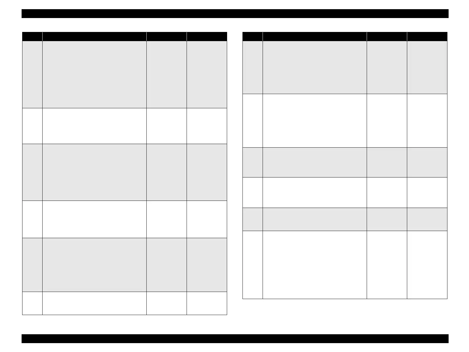
12
Continuity check of HARNESS ASSY 2BTR
SENS
Disconnect P/J620 from HARNESS ASSY
2BTR SENS.
Do all of the wiring below have normal
continuity?
P620-1 ↔ J111-3
P620-2 ↔ J111-2
P620-3 ↔ J111-1
Replace
SENSOR
FUSER IN.
(p.369)
Replace
HARNESS
ASSY 2BTR
SENS.
13
Shape and operation check of CAM ASSY-
2ND
Does CAM ASSY 2ND move smoothly
without any damage, and does it enter the
sensor sensing area?
Go to Step [14]. Replace CAM
ASSY-2ND.
(p.376)
14
Operation check of SENSOR 2BTR
RETRACT
Remove 2ND BTR ASSY. (p.374)
The voltage of P418-6 ↔ P418-5 on PWBA
MCU is 0 VDC when Actuator of CAM ASSY-
2ND enters the sensing area of SENSOR 2BTR
RETRACT, and is 5 VDC when it leaves the
sensing area?
Go to Step [19]. Go to Step [15].
15
5 VDC power supply check to SENSOR
2BTR RETRACT
Disconnect P/J418 from PWBA MCU.
The voltage of P418-4 ↔ P418-5 on PWBA
MCU is 5 VDC?
Go to Step [16]. Go to Step [17].
16
Continuity check of HARNESS ASSY ADC
Disconnect P/J418 from PWBA MCU.
Do all of the wiring below have normal
continuity?
J418-4 ↔ J112-3
J418-5 ↔ J112-2
J418-6 ↔ J112-1
Replace
SENSOR 2BTR
RETRACT.
(p.382)
Replace
HARNESS
ASSY ADC.
17
5 VDC power supply check to PWBA MCU
The voltage of P410-3 ↔ P410-4 on PWBA
MCU is 5 VDC?
Replace PWBA
MCU. (p.432)
Go to Step [18].
Step Check Yes No
18
Continuity check of HARNESS ASSY MAIN
Disconnect P/J410 from PWBA MCU and P/
J502 from LV/HVPS.
Do all of the wiring below have normal
continuity?
J410-3 ↔ J502-3
J410-4 ↔ J502-4
Replace LV/
HVPS. (p.435)
Repair broken or
shorted part.
19
Continuity check of HARNESS ASSY MAIN
Disconnect the P/J403 from PWBA MCU.
Do all of the wiring below have normal
continuity?
J403-1 ↔ J600-3
J403-2 ↔ J600-2
J403-3 ↔ J600-1
Go to Step [20]. Repair broken or
shorted part.
20
24 VDC power supply check to MOT ASSY
MICRO (2nd BTR Retract Motor)
The voltage of P403-3 ↔ P403-2 on PWBA
MCU is 24 VDC?
Go to Step [21]. Go to Step [22].
21
Check after replacement of MOT ASSY
MICRO
Replace MOT ASSY MICRO. (p.427)
Does the error recur when a test print is made?
Replace PWBA
MCU. (p.432)
End of procedure
22
24 VDC power supply check to PWBA MCU
The voltage of P410-5/6 ↔ P410-7/8 on
PWBA MCU is 24 VDC?
Replace PWBA
MCU. (p.432)
Go to Step [23].
23
Continuity check of HARNESS ASSY MAIN
Disconnect P/J410 from PWBA MCU and P/
J502 from LV/HVPS.
Do all of the wiring below have normal
continuity?
J410-5 ↔ J502-5
J410-6 ↔ J502-6
J410-7 ↔ J502-7
J410-8 ↔ J502-8
Replace LV/
HVPS. (p.435)
Repair broken or
shorted part.
Step Check Yes No
manuals4you.commanuals4you.com
 Loading...


