EPSON AcuLaser CX11/CX11F Revision B
DISASSEMBLY AND ASSEMBLY ADF Section 500
REINSTALLATION
1. Viewed from the direction as shown in Figure 4-184, insert the left pintle of the
ADF BASE ASSY into the left bearing of the ADF FRAME ASSY, and push the
right frame of the ADF FRAME ASSY outward to insert the right pintle into the
right bearing of the ADF FRAME ASSY. See Figure 4-184.
2. Secure the harnesses of the ADF FRAME ASSY into the notch of the ADF BASE
ASSY. See Figure 4-183.
3. Secure the harnesses of the ADF BASE ASSY with the two CABLE TIEs. See
Figure 4-183.
4. Bundle the harnesses of the ADF BASE ASSY, wind them around the ferrite core
once, and then secure the ferrite core to the harnesses with the tie.
5. Install the ADF FRAME ASSY to the SDH COVER matching the positioning
hole of the ADF FRAME ASSY with the guide pin of the SDH COVER.
6. Attach the COVER SPRING ASSY to the ADF FRAME ASSY matching the
positioning hole of the COVER SPRING ASSY with the guide pin of the ADF
FRAME ASSY, and secure them to the SDH COVER with the four screws (M3 x
8 mm, P-type, A-head).
7. Connect the CABLE connector of the ADF FRAME ASSY and the ADF BASE
ASSY to the ADF PCB ASSY.
8. Attach the ADF COVER C. (p496)
9. Attach the ADF COVER R. (p492)
10. Attach the ADF Unit. (p481)
11. Install the Scanner. (p306)
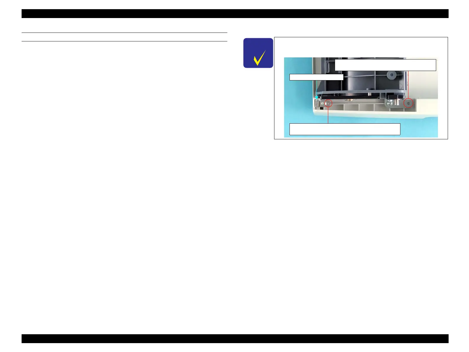
C H E C K
P O I N T
When attaching the ADF FRAME ASSY to the SDH COVER,
make sure to match the positioning hole and the guide pin.
COVER SPRING ASSY
Guide Pin of the SDH COVER and Positioning
Hole of the ADF FRAME ASSY
Guide Pin of the ADF FRAME ASSY and
Positioning Hole of the COVER SPRING ASSY
manuals4you.commanuals4you.com
 Loading...


