Coprocessor Interface
ARM DDI 0301H Copyright © 2004-2009 ARM Limited. All rights reserved. 11-9
ID012310 Non-Confidential, Unrestricted Access
11.3 Token queue management
The token queues, all of which are three slots long and function identically, are implemented as
short FIFOs. The following sections describe an example implementation of the queues:
• Queue implementation
• Queue modification
• Queue flushing on page 11-11.
11.3.1 Queue implementation
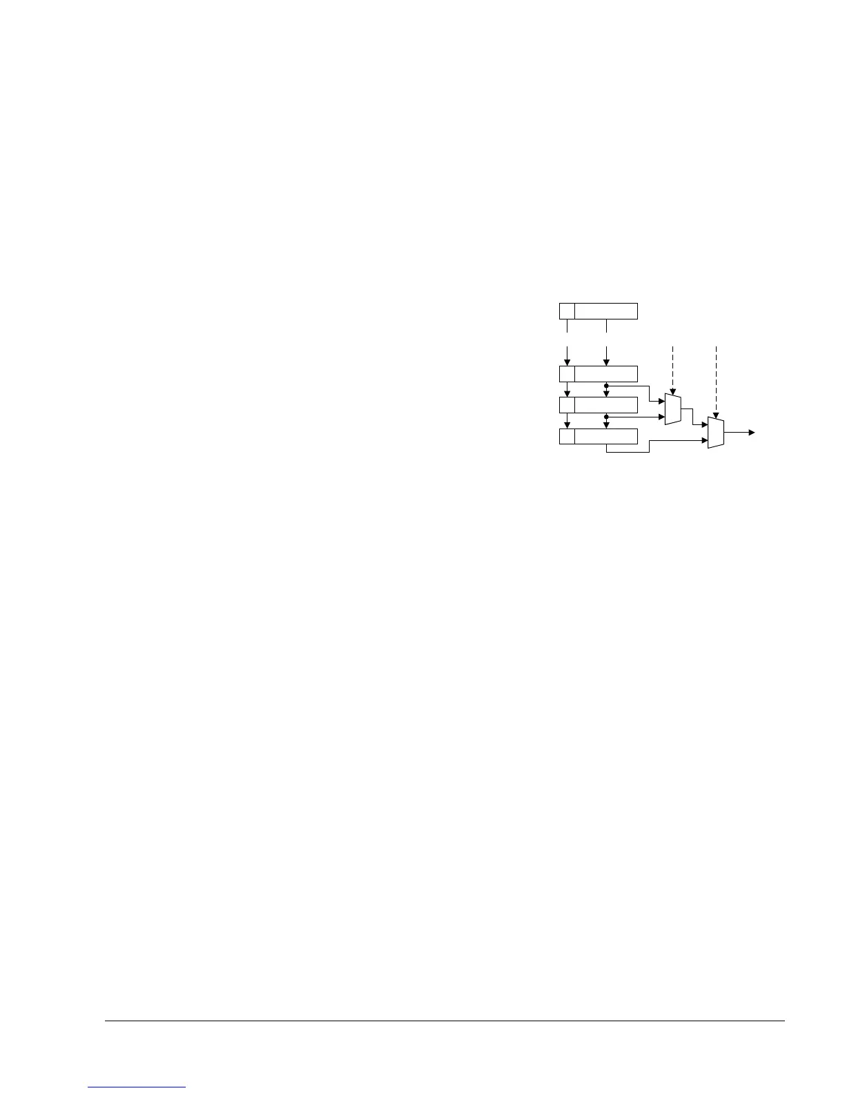
The queue FIFOs are implemented as three registers, with the current output selected by using
multiplexors. Figure 11-4 shows this arrangement.
Figure 11-4 Token queue buffers
The queue consists of three registers. Each of these is associated with a flag that indicates if the
register contains valid data. New data are moved into the queue by being written into buffer A
and continue to move along the queue if the next register is empty, or is about to become empty.
If the queue is full, the oldest data, and therefore the first to be read from the queue, occupies
buffer C and the newest occupies buffer A.
The multiplexors also select the current flag, that then indicates whether the selected output is
valid.
11.3.2 Queue modification
The queue is written to on each cycle. Buffer A accepts the data arriving at the interface, and the
buffer A flag accepts the valid bit associated with the data. If the queue is not full, this results in
no loss of data because the contents of buffer A are moved to buffer B during the same cycle.
If the queue is full, then the loading of buffer A is inhibited to prevent loss of data. In any case,
no valid data is presented by the interface when the queue is full, so no data loss ensues.
The state of the three buffer flags is used to decide the buffer that provides the queue output
during each cycle. The output is always provided by the buffer containing the oldest data. This
is buffer C if it is full, or buffer B or, if that is empty, buffer A.
Buffer AA
Buffer BB
Buffer CC
OutputV
Interconnect
Out
S1S0
0
1
0
1
 Loading...

