Programmer’s Model
ARM DDI 0301H Copyright © 2004-2009 ARM Limited. All rights reserved. 2-22
ID012310 Non-Confidential, Unrestricted Access
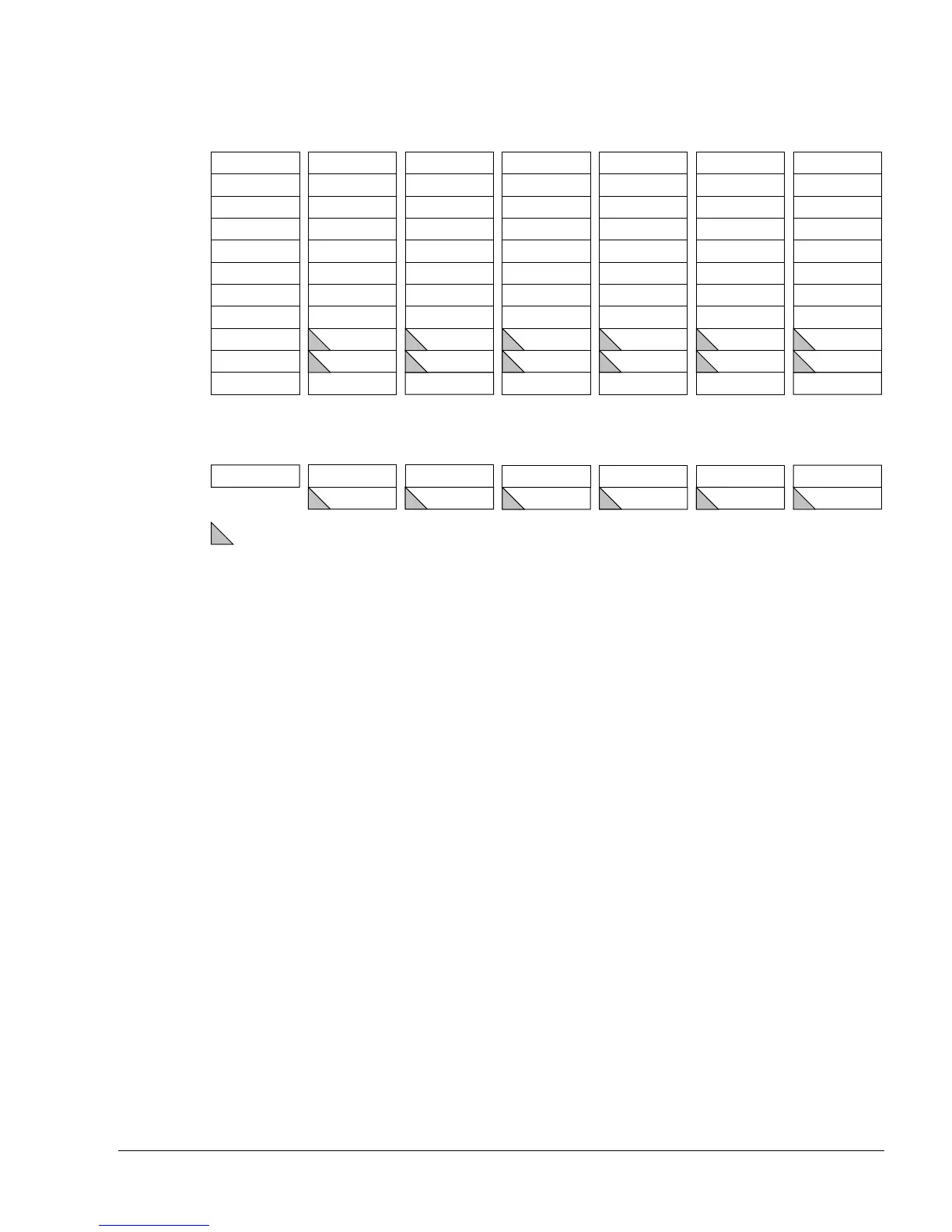
Figure 2-8 Register organization in Thumb state
2.9.3 Accessing high registers in Thumb state
In Thumb state, the high registers, R8–R15, are not part of the standard core register set. You
can use special variants of the MOV instruction to transfer a value from a low register, in the
range R0–R7, to a high register, and from a high register to a low register. The CMP instruction
enables you to compare high register values with low register values. The ADD instruction
enables you to add high register values to low register values. For more details, see the ARM
Architecture Reference Manual.
2.9.4 ARM state and Thumb state registers relationship
Figure 2-9 on page 2-23 shows the relationships between the Thumb state and ARM state
registers. See the Jazelle V1 Architecture Reference Manual for details of Jazelle state registers.
Thumb state general registers and program counter
System and
User
Thumb state program status registers
= banked register
Supervisor Abort IRQ Undefined
R0
R1
R2
R3
R4
R5
R6
R7
SP
LR
PC
FIQ
R0
R1
R2
R3
R4
R5
R6
R7
SP_fiq
LR_fiq
PC
R0
R1
R2
R3
R4
R5
R6
R7
SP_svc
LR_svc
R0
R1
R2
R3
R4
R5
R6
R7
SP_abt
LR_abt
R0
R1
R2
R3
R4
R5
R6
R7
SP_irq
LR_irq
R0
R1
R2
R3
R4
R5
R6
R7
SP_und
LR_und
CPSR CPSR CPSR
CPSR CPSR CPSR
SPSR_fiq SPSR_svc
SPSR_abt SPSR_irq
SPSR_und
PC PC PC PC
Secure
monitor
R0
R1
R2
R3
R4
R5
R6
R7
SP_mon
LR_mon
CPSR
SPSR_mon
PC