Power Control
ARM DDI 0301H Copyright © 2004-2009 ARM Limited. All rights reserved. 10-8
ID012310 Non-Confidential, Unrestricted Access
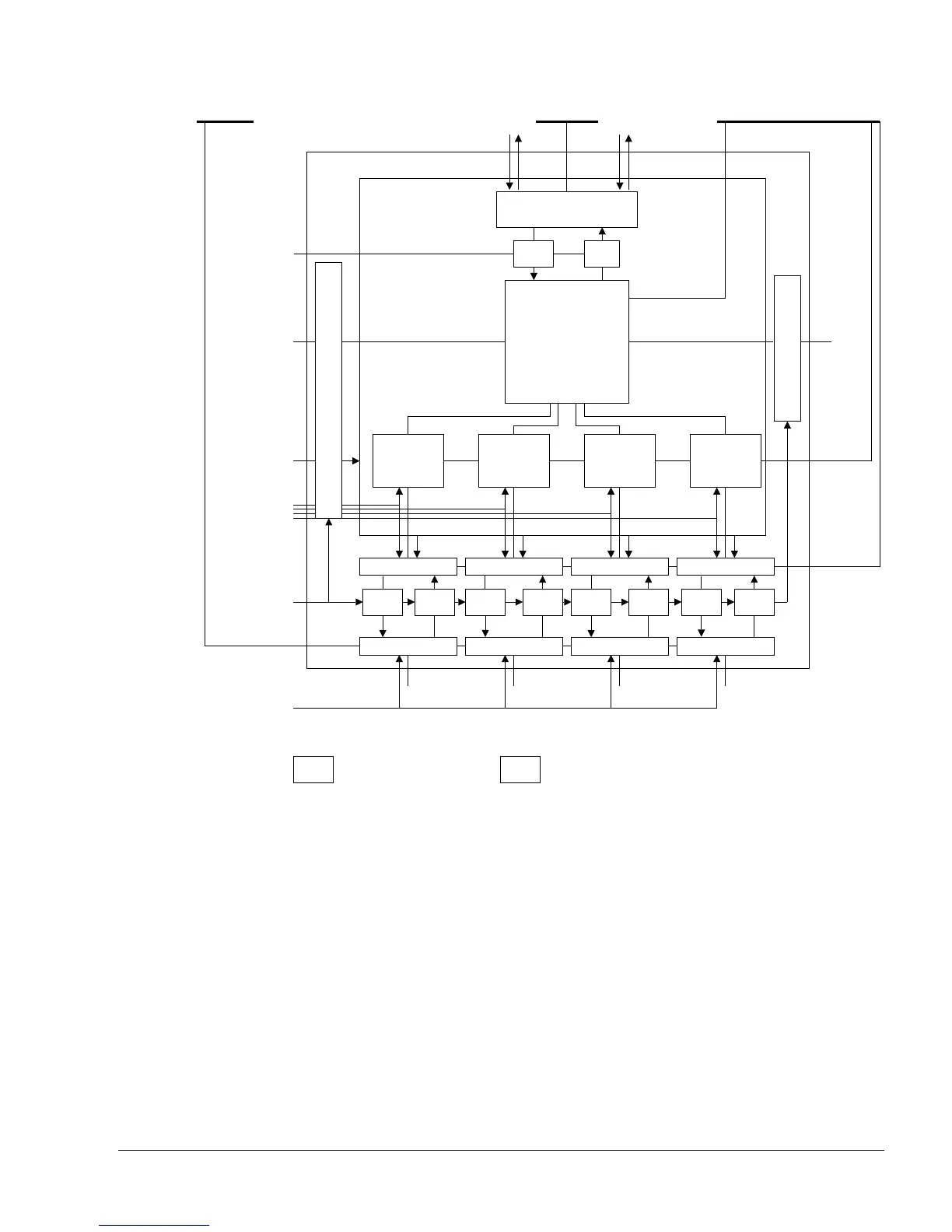
Figure 10-1 IEM structure
10.4.3 Operation of IEM
IEM balances performance and power consumption by dynamic alteration of the processor
clock frequency and supply voltage. CPUCLAMP is provided to control the clamp cells
between VCore and VSoc. Figure 10-1 shows this.
10.4.4 Use of IEM
To use IEM the processor must be implemented with appropriate register slices and included in
a SoC that contains an Intelligent Energy Controller (IEC
™
). For example systems, see the
Intelligent Energy Controller Technical Overview.
IEM is functionally transparent to the user.
RAMs
Core
Instruction
level 2
interface
DMA level
2 interface
Up level shift and clamp
Processor
Clock enables
CLKIN
ACLK clocks
VCoreSliceI
Data read/
write level
2 interface
Peripheral
level 2
interface
Down level shift and clamp
CLK
Level 2
VCoreSliceRW VCoreSliceD VCoreSliceP
CLK CLK CLK
V
DD
SoC
V
DD
RAM
V
DD
core
RAMCLAMP
VSoCSliceI VSoCSliceRW VSoCSliceD VSoCSliceP
Down Up
Up
CPUCLAMP
DownUpDownUpDownUpDown
Test,
debug,
VIC,
and
other
outputs
Up DownUp level shifter and clamp Down level shifter and clamp
Test,
debug,
VIC, and
other
inputs
Coprocessor interface ETM interface