System Control Coprocessor
ARM DDI 0301H Copyright © 2004-2009 ARM Limited. All rights reserved. 3-149
ID012310 Non-Confidential, Unrestricted Access
3.2.60 c15, TLB lockdown access registers
The purpose of the TLB lockdown access registers is to provide read and write access to the
contents of the lockdown region of the TLB. The processor requires these registers to enable it
to save state before it enters Dormant mode, see Dormant mode on page 10-4. You might also
use this register for debug.
The TLB lockdown access registers are:
• in CP15 c15
• four 32-bit read/write registers in the Secure world only:
— TLB Lockdown Index Register
— TLB Lockdown VA Register
— TLB Lockdown PA Register
— TLB Lockdown Attributes Register.
• accessible in privileged modes only.
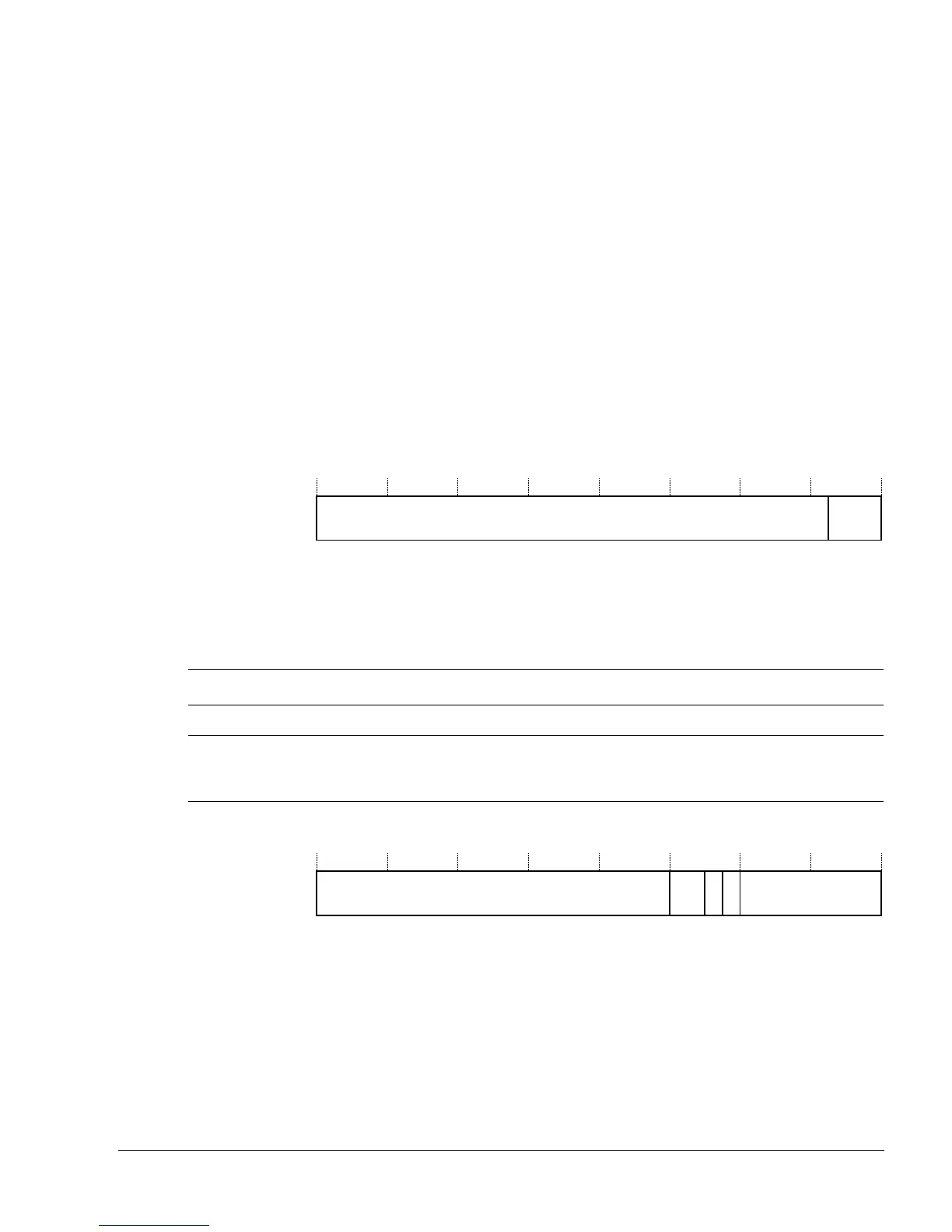
The four registers have different bit arrangements and functions. Figure 3-76 shows the
arrangement of bits in the TLB Lockdown Index Register.
Figure 3-76 TLB Lockdown Index Register format
Table 3-148 lists how the bit values correspond with the TLB Lockdown Index Register
functions.
Figure 3-77 shows the arrangement of bits in the TLB Lockdown VA Register.
Figure 3-77 TLB Lockdown VA Register format
IndexUNP/SBZ
31 32 0
Table 3-148 TLB Lockdown Index Register bit functions
Bits Field name Function
[31:3] - UNP/SBZ.
[2:0] Index Selects the lockdown entry of the eight TLB lockdown entries to read or write when accessing
other TLB lockdown access registers.
Select lockdown entry 0 to 7.
VA
31 12 11 10 9 8 7 0
SBZ G
S
B
Z
ASID