Debug Test Access Port
ARM DDI 0301H Copyright © 2004-2009 ARM Limited. All rights reserved. 14-17
ID012310 Non-Confidential, Unrestricted Access
• The InstCompl flag must be set when the DSCR[13] execute ARM instruction enable bit
is changed from 1 to 0. Otherwise, the behavior of the core is Unpredictable. If the
DSCR[13] flag is cleared correctly, none of the registers and flags are altered.
• When the core leaves Debug state, none of the registers and flags are altered.
Scan chain 6
Purpose Embedded Trace Macrocell.
Length 1 + 7 + 32 = 40 bits.
Description This scan chain accesses the register map of the Embedded Trace Macrocell. See
the description in the programmer’s model chapter in the Embedded Trace
Macrocell Architecture Specification for details of register allocation.
To access this scan chain you must select INTEST. Accesses to scan chain 6 with
EXTEST selected are ignored. In scan chain 6 you must use the nRW bit, bit[39],
to distinguish between reads and writes, as the Embedded Trace Macrocell
Architecture Specification describes.
Note
For scan chain 6, the use of INTEST and EXTEST differs from their standard use
that the start of this section describes.
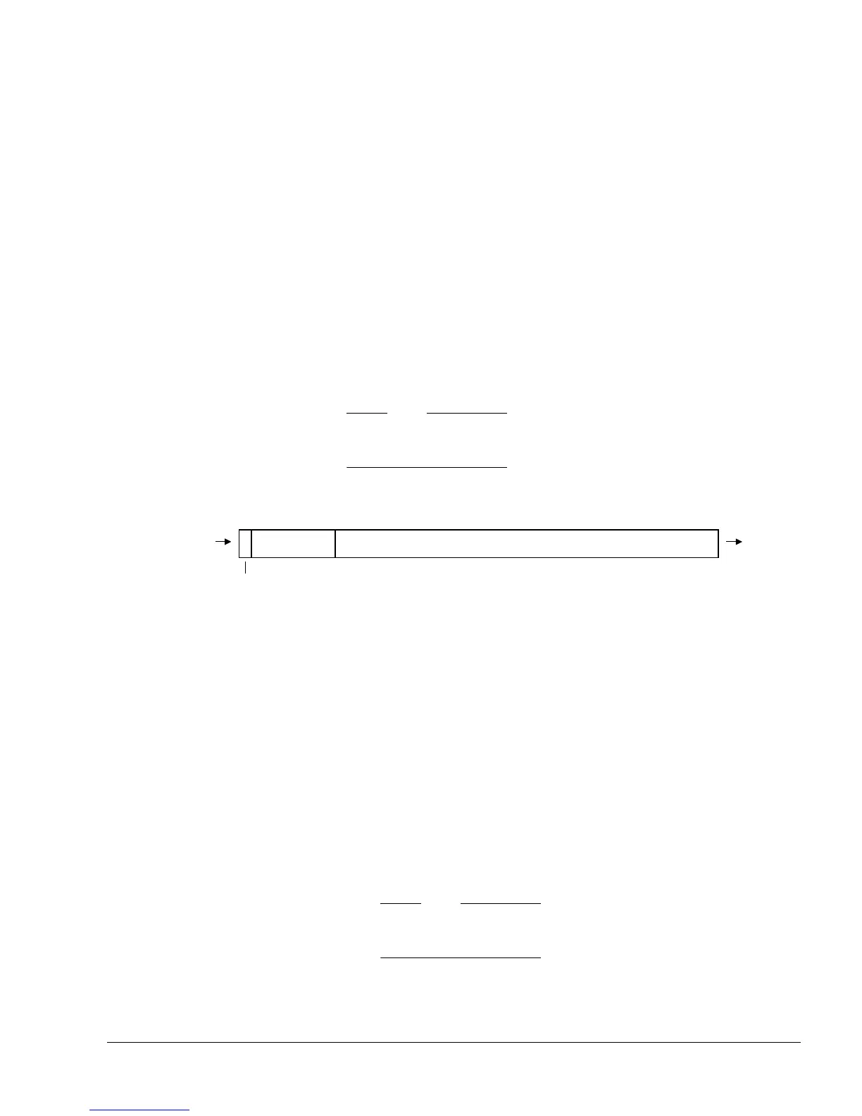
Order Figure 14-12 shows the order of bits in scan chain 6.
Figure 14-12 Scan chain 6 bit order
Scan chain 7
Purpose Debug.
Length 7 + 32 + 1 = 40 bits.
Description Scan chain 7 accesses the VCR, PC, BRPs, and WRPs. The accesses are
performed with the help of read or write request commands. A read request copies
the data held by the addressed register into scan chain 7. A write request copies
the data held by the scan chain into the addressed register. When a request is
finished the ReqCompl flag is set. The DBGTAP debugger must poll it and check
it is set before another request can be issued. The exact behavior of the scan chain
is as follows:
• Either INTEST or EXTEST must be selected. INTEST and EXTEST have
the same meaning in this scan chain.
Note
For scan chain 7, the use of INTEST and EXTEST differs from the standard
use that the start of this section describes.
• If the value captured by the Ready/nRW bit at the Capture-DR state is 1, the
data that is being shifted in generates a request at the Update-DR state. The
Address field indicates the register being accessed, see Table 14-2 on
DBGTDI DBGTDO
Address[6:0]
39 32 31 0
Data[31:0]
38
nRW
 Loading...

