Debug
ARM DDI 0301H Copyright © 2004-2009 ARM Limited. All rights reserved. 13-21
ID012310 Non-Confidential, Unrestricted Access
For the second case a WRP and a BRP with context ID comparison capability have to be linked.
A debug event is generated when both the DMVA and the context ID pair match simultaneously.
Table 13-14 lists the bit field definitions for the Watchpoint Value Registers.
13.3.10 CP14 c112-c113, Watchpoint Control Registers (WCR)
These registers contain the necessary control bits for setting:
• watchpoints
• linked watchpoints.
Table 13-15 lists the Watchpoint Control Registers that the processor implements.
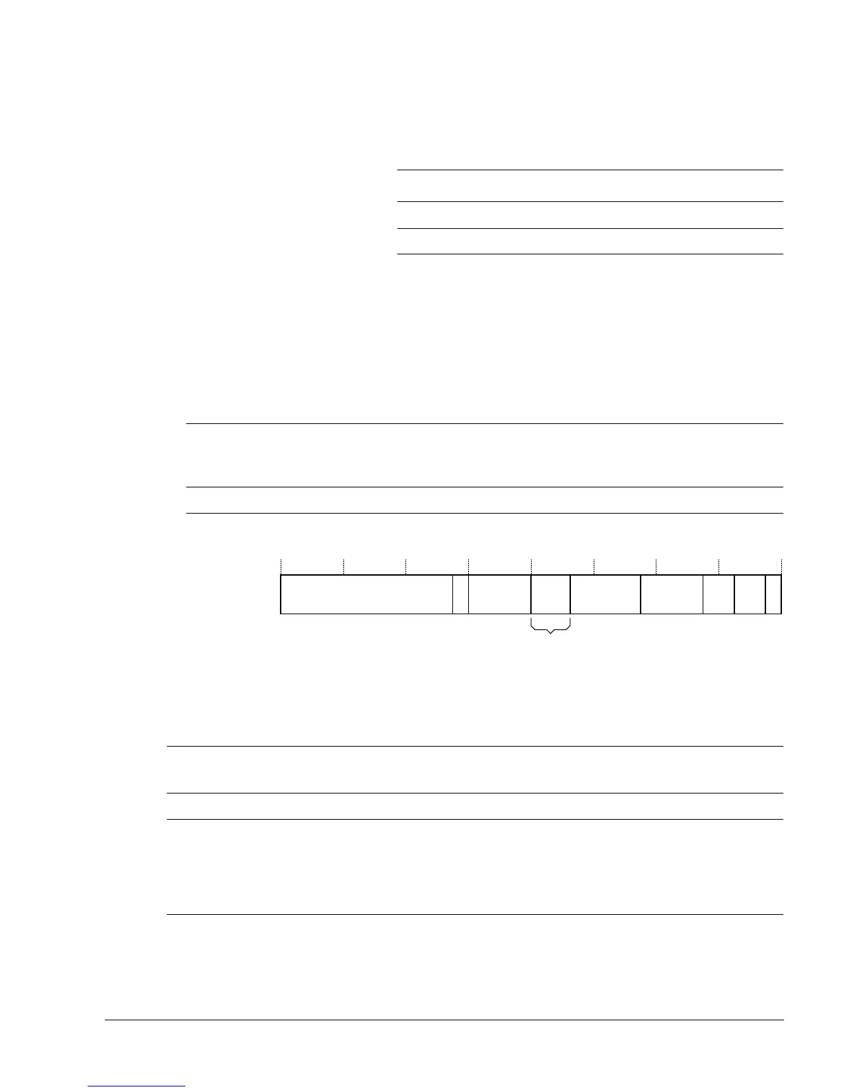
Figure 13-7 shows the format of the Watchpoint Control Registers.
Figure 13-7 Watchpoint Control Registers, format
Table 13-16 lists the bit field definitions for the Watchpoint Control Registers.
Table 13-14 Watchpoint Value Registers, bit field definitions
Bits Read/write attributes Reset value Description
[31:2] RW - Watchpoint address
[1:0] UNP/SBZP - -
Table 13-15 Processor Watchpoint Control Registers
Binary address
Register
number
CP14 debug register name Abbreviation
Context ID
capable?
Opcode_2 CRm
b111 b0000-b0001 c112-c113 Watchpoint Control Registers 0-1 WCR0-1 -
WUNP/SBZP
31
21
20 19 16 15 9 8 5 4 3 2 1 0
E Linked BRP
Byte
address
select
L/S S
WUNP/SBZP
31
21
20 19 16 15 9 8 5 4 3 2 1 0
E Linked BRP UNP/SBZP
Byte
address
select
L/S S
14 13
Secure watchpoint match
Table 13-16 Watchpoint Control Registers, bit field definitions
Bits
Read/write
attributes
Reset
value
Description
[31:21] UNP/SBZP - Reserved.
[20] RW - Enable linking bit:
0 = Linking disabled
1 = Linking enabled.
When this bit is set, this watchpoint is linked with the context ID holding BRP
selected by the linked BRP field.
[19:16] RW - Linked BRP. The binary number encoded here indicates a context ID holding BRP
to link this WRP with.