Operation Manual – Routing Protocol
H3C S3600 Series Ethernet Switches-Release 1510 Chapter 2
Static Route Configuration
2-4
2.4 Static Route Configuration Example
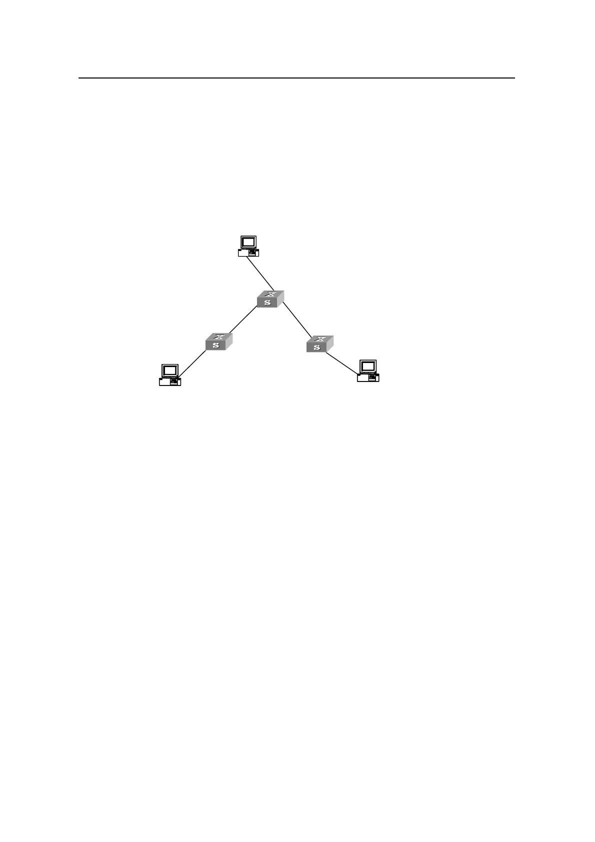
I. Network requirements
As shown in Figure 2-1, the masks of all the IP addresses in the figure are
255.255.255.0. It is required that all the hosts/Ethernet switches in the figure can
interconnect with each other by configuring static routes.
II. Network diagram
Host A
1.1.5.2/24
1.1.5.1/24
1.1.2.2/24
1.1.2.1/24
1.1.1.1/24
1.1.1.2/24
1.1.3.1/24
1.1.3.2/
Sw itc h A
Sw itc h B
Sw itc h C
1.1.4.2/24
24
1.1.4.1/24
Host C
Host B
Host A
1.1.5.2/24
1.1.5.1/24
1.1.2.2/24
1.1.2.1/24
1.1.1.1/24
1.1.1.2/24
1.1.3.1/24
1.1.3.2/
Sw itc h A
Sw itc h B
Sw itc h C
1.1.4.2/24
24
1.1.4.1/24
Host CHost C
Host BHost B
Figure 2-1 Static route configuration
III. Configuration procedure
Perform the following steps on the switch:
# Configure static routes on SwitchA.
[SwitchA] ip route-static 1.1.3.0 255.255.255.0 1.1.2.2
[SwitchA] ip route-static 1.1.4.0 255.255.255.0 1.1.2.2
[SwitchA] ip route-static 1.1.5.0 255.255.255.0 1.1.2.2
# Configure static routes on SwitchB.
[SwitchB] ip route-static 1.1.2.0 255.255.255.0 1.1.3.1
[SwitchB] ip route-static 1.1.5.0 255.255.255.0 1.1.3.1
[SwitchB] ip route-static 1.1.1.0 255.255.255.0 1.1.3.1
# Configure static routes on SwitchC.
[SwitchC] ip route-static 1.1.1.0 255.255.255.0 1.1.2.1
[SwitchC] ip route-static 1.1.4.0 255.255.255.0 1.1.3.2
Perform the following steps on the host:
# Configure the default gateway of Host A to 1.1.5.1. Detailed configuration procedure
is omitted.

 Loading...


