Operation Manual – MSTP
H3C S3600 Series Ethernet Switches-Release 1510 Chapter 1
MSTP Configuration
1-47
[H3C] stp instance 4 root primary
4) Configure Switch D
# Enter MST region view.
<H3C> system-view
[H3C] stp region-configuration
# Configure the MST region.
[H3C-mst-region] region-name example
[H3C-mst-region] instance 1 vlan 10
[H3C-mst-region] instance 3 vlan 30
[H3C-mst-region] instance 4 vlan 40
[H3C-mst-region] revision-level 0
# Activate the settings of the MST region manually.
[H3C-mst-region] active region-configuration
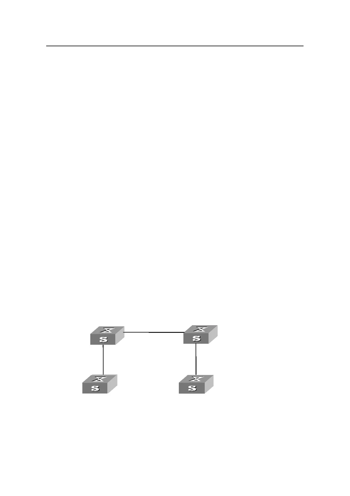
1.11 VLAN-VPN tunnel Configuration Example
I. Network requirements
z S3600 series Ethernet switches operate as the access devices of the operator’s
network, that is, Switch C and Switch D in the network diagram.
z S3100 series switches operate as the access devices of the user’s network, that is,
Switch A and Switch B in the network diagram.
z Switch C and Switch D are connected to each other through the configured trunk
ports of the switches. The VLAN-VPN tunnel function is enabled in system view,
thus implementing transparent transmission between the user’s network and the
operator’s network.
II. Network diagram
Switch C
Switch A
Switch D
Switch B
E 1/0/2
E 1/0/1
Switch C
Switch A
E 1/0/1
Switch D
Switch B
E 1/0/2
Switch C
Switch A
Switch D
Switch B
E 1/0/2
E 1/0/1
Switch C
Switch A
E 1/0/1
E1/ 0/1
Switch D
Switch B
E 1/0/1
E 1/0/2
Switch C
Switch A
Switch D
Switch B
E 1/0/2
E 1/0/1
Switch C
Switch A
E 1/0/1
Switch D
Switch B
E 1/0/2
Switch C
Switch A
Switch D
Switch B
E 1/0/2
E 1/0/1
Switch C
Switch A
E 1/0/1
E1/ 0/1
Switch D
Switch B
E 1/0/1
E 1/0/2
Figure 1-8 Network diagram for VLAN-VPN tunnel configuration

 Loading...


