Operation Manual – VLAN-VPN
H3C S3600 Series Ethernet Switches-Release 1510 Chapter 2
BPDU Tunnel Configuration
2-2
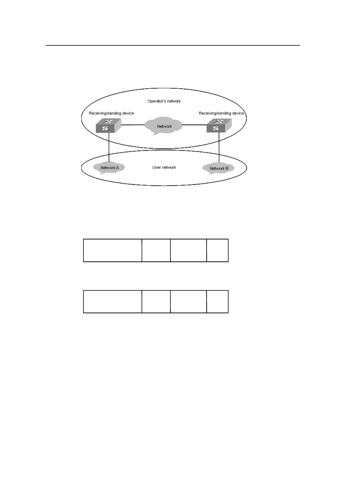
ensures the data portion of the packet is consistent with that before the packet
enters the tunnel. So, a tunnel here acts as a local link for user devices. It enables
Layer 2 protocol packets to travel across a logical LAN.
Figure 2-1 BPDU Tunnel network hierarchy
Figure 2-2 and Figure 2-3 show the structure of a BPDU packet before and after it enter
a BPDU tunnel.
BPDU Data FCS
Destination MAC address
(Protocol-specific MAC)
Source MAC
address
BPDU Data FCS
Destination MAC address
(Protocol-specific MAC)
Source MAC
address
Figure 2-2 The structure of a BPDU packet before it enters a BPDU tunnel
BPDU Data FCS
Destination MAC address
(Recognizable by user)
Source MAC
address
BPDU Data FCS
Destination MAC address
(Recognizable by user)
Source MAC
address
Figure 2-3 The structure of a BPDU packet after it enters a BPDU tunnel
2.2 BPDU Tunnel Configuration
You can establish BPDU tunnels between S3600 series Ethernet switches for the
packets of the following protocols:
z ALCP (link aggregation control protocol)
z NDP (neighbor discovery protocol)
z Proprietary protocols, including CDP and VTP

 Loading...


