Operation Manual – DHCP
H3C S3600 Series Ethernet Switches-Release 1510 Chapter 5
DHCP Accounting Configuration
5-2
5.2.2 Configuring DHCP Accounting
Table 5-1 Configure DHCP accounting
Operation Command Description
Enter system view
system-view
—
Enter address pool
view
dhcp server ip-pool
pool-name
Required
Enable DHCP
accounting
accounting domain
domain-name
Required
The domain identified by the
domain-name argument can be
created by using the domain
command.
5.2.3 DHCP Accounting Configuration Example
I. Network requirements
z The DHCP server connects to a DHCP client and a RADIUS server respectively
through its Ethernet1/0/2 and Ethernet1/0/1 ports.
z Ethernet1/0/2 belongs to VLAN 2; Ethernet1/0/1 belongs to VLAN 3.
z The IP address of VLAN 2 interface is 10.1.1.1/24, and that of VLAN 3 interface is
10.1.2.1/24.
z The IP address of the RADIUS server is 10.1.2.2/24.
z DHCP accounting is enabled on the DHCP server.
z The IP addresses of the global DHCP address pool belongs to the network
segment 10.1.1.0/24. The DHCP server operates as a RADIUS client and adopts
AAA for authentication.
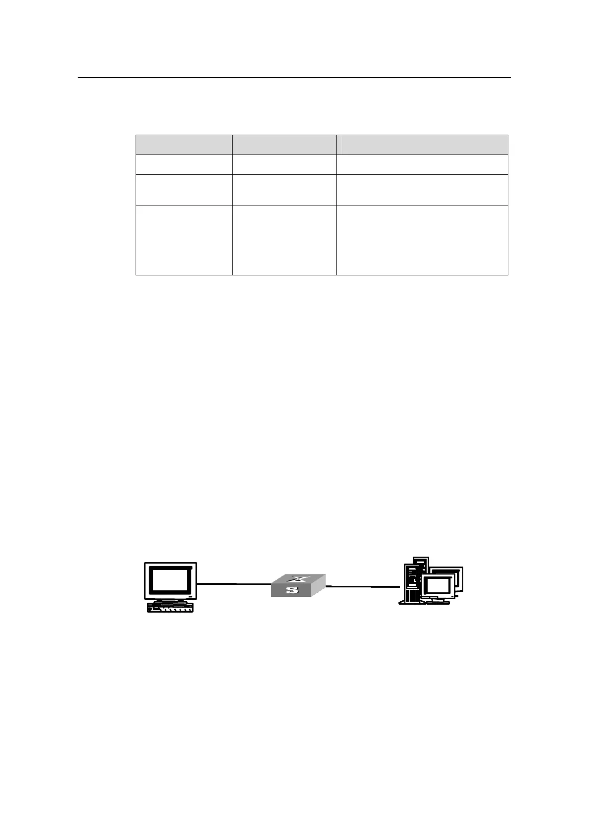
II. Network diagram
RADIUS server
10.1.2.2/24
DHCP client
DHCP server
Ethernet 1/0/1
Vlan 3
10.1.2.1/24
Ethernet 1/0/2
Vlan 2
10.1.1.1/24
10.1.2.2/24
Ethernet 1/0/1
10.1.2.1/24
Ethernet 1/0/
10.1.1.1/24
10.1.2.2/24
Ethernet 1/0/1
10.1.2.1/24
Ethernet 1/0/2
10.1.1.1/24
10.1.2.2/24
10.1.2.2/24
Ethernet 1/0/1
10.1.2.1/24
Ethernet 1/0/2
10.1.1.1/24
10.1.2.2/24
Ethernet 1/0/1
10.1.2.1/24
Ethernet 1/0/
10.1.1.1/24
RADIUS server
10.1.2.2/24
DHCP client
RADIUS server
10.1.2.2/24
DHCP client
DHCP server
Ethernet 1/0/1
Vlan 3
10.1.2.1/24
Ethernet 1/0/2
Vlan 2
10.1.1.1/24
10.1.2.2/24
DHCP server
Ethernet 1/0/1
Vlan 3
10.1.2.1/24
Ethernet 1/0/2
Vlan 2
10.1.1.1/24
10.1.2.2/24
Ethernet 1/0/1
10.1.2.1/24
Ethernet 1/0/
10.1.1.1/24
10.1.2.2/24
Ethernet 1/0/1
10.1.2.1/24
Ethernet 1/0/
10.1.1.1/24
10.1.2.2/24
Ethernet 1/0/1
10.1.2.1/24
Ethernet 1/0/2
10.1.1.1/24
10.1.2.2/2410.1.2.2/24
10.1.2.2/24
Ethernet 1/0/1
10.1.2.1/24
Ethernet 1/0/2
10.1.1.1/24
10.1.2.2/24
Ethernet 1/0/1
10.1.2.1/24
Ethernet 1/0/2
10.1.1.1/24
10.1.2.2/24
Ethernet 1/0/1
10.1.2.1/24
Ethernet 1/0/2
10.1.1.1/24
10.1.2.2/24
Ethernet 1/0/1
10.1.2.1/24
Ethernet 1/0/
10.1.1.1/24
Figure 5-1 Network diagram for DHCP accounting configuration
III. Configuration procedure
# Enter system view.
<H3C> system-view
# Create VLAN 2.

 Loading...


