Operation Manual – VRRP
H3C S3600 Series Ethernet Switches-Release 1510 Chapter 1
VRRP Configuration
1-18
z When the connection between Switch B and Switch C fails, Switch D becomes the
Master in backup group 1 automatically and the link from Switch D to Switch C,
namely the secondary link, is enabled.
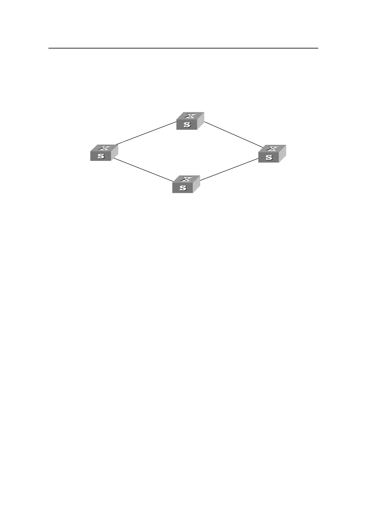
II. Network diagram
192.168.1.2
20.1.1.2
10.1.1.3
Switch
10.1.1.4
C
192.168.1.1/24
192.168.1.2/24
192.168.1.3/24
20.1.1.3/24
10.1.1.3/24
Ethernet 1/0/1
Ethernet 2/0/1
Switch A
Switch B
Switch
Switch D
VLAN 1
VLAN 1
VLAN 1
VLAN 1
10.1.1.4/24
C
20.1.1.4/24
192.168.1.2
20.1.1.2
10.1.1.3
Switch
10.1.1.4
C
192.168.1.1/24
192.168.1.2/24
192.168.1.3/24
20.1.1.3/24
10.1.1.3/24
Ethernet 1/0/1
Ethernet 2/0/1
Switch A
Switch B
Switch
Switch D
VLAN 1
VLAN 1
VLAN 1
VLAN 1
10.1.1.4/24
C
20.1.1.4/24
Figure 1-7 Network diagram for implementing the auto detect function in VRRP
III. Configuration procedure
z Configure Switch B.
# Create detecting group 9.
<H3C B> system-view
[H3C B] detect-group 9
# Specify to detect the reachability of the IP address 10.1.1.4, setting the detect number
to 1.
[H3C B-detect-group-9] detect-list 1 ip address 10.1.1.4
[H3C B-detect-group-9] quit
# Assign an IP address to VLAN-interface1.
[H3C B] interface vlan-interface 1
[H3C B-Vlan-interface1] ip address 192.168.1.2 24
# Enable VRRP on VLAN-interface1 and assign a virtual IP address to the backup
group.
[H3C B-Vlan-interface1] vrrp vrid 1 virtual-ip 192.168.1.10
# Set the backup group priority of switch B to 110, and specify to decrease the priority
by 20 when the result of detecting group 9 is unreachable.
[H3C B-Vlan-interface1] vrrp vrid 1 priority 110
[H3C B-Vlan-interface1] vrrp vrid 1 track detect-group 9 reduced 20
z Configure Switch D.
# Assign an IP address to VLAN-interface1.
<H3C D> system-view
 Loading...


