Operation Manual – VRRP
H3C S3600 Series Ethernet Switches-Release 1510 Chapter 1
VRRP Configuration
1-17
z Enable the port tracking function on Ethernet1/0/1 port of the master switch and
specify that the priority of the master decreases by 50 when Ethernet1/0/1 port
fails, which triggers new master switch being determined in the backup group 1.
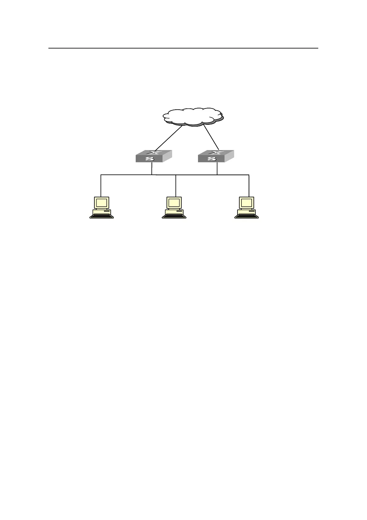
II. Network diagram
Ethernet
Mas ter
Host 1Host 2H
10.100.10.7 10.100.10.8
Virtual IP address10.100.10.1
Network
ost 3
10.100.10.9
Backup
ess10.100.10.1
ess10.100.10.3
Virtual IP addr
Actual IP address10.100.10.2 Actual IP addr
Netw ork
Ethernet
Mas ter
Host 1Host 2H
10.100.10.7 10.100.10.8
Virtual IP address10.100.10.1
Network
ost 3
10.100.10.9
Backup
ess10.100.10.1
ess10.100.10.3
Virtual IP addr
Actual IP address10.100.10.2 Actual IP addr
Netw ork
Figure 1-6 Network diagram for VRRP port tracking configuration
III. Configuration procedure
z Configure the master switch.
# Enter system view.
<H3C> system-view
# Create VLAN 2.
[H3C] vlan 2
[H3C-vlan2] port Ethernet1/0/1
[H3C-vlan2] quit
# Enter Ethernet1/0/1 port view and enable the port tracking function.
[H3C] interface Ethernet1/0/1
[H3C-Ethernet1/0/1] vrrp vlan-interface 2 vrid 1 track reduced 50
1.4.5 VRRP Auto Detect Configuration Example
I. Network requirements
z Switch B and switch D form VRRP backup group 1, whose virtual IP address is
192.168.1.10. Normally, packets sourced from Switch A and destined for Switch C
are forwarded by Switch B.

 Loading...


