Operation Manual – VLAN-VPN
H3C S3600 Series Ethernet Switches-Release 1510 Chapter 2
BPDU Tunnel Configuration
2-4
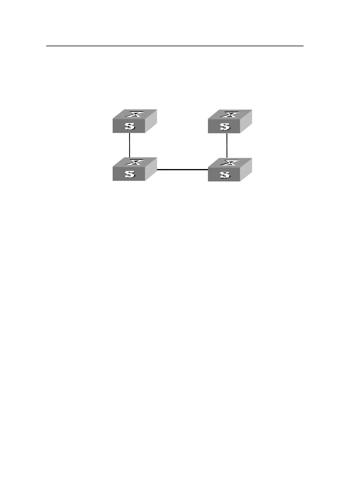
z Enable the BPDU Tunnel function for NDP packets on the Ethernet1/0/1 and
Ethernet1/0/4 port shown in the
Figure 2-4.Set the port Ethernet1/0/2 and
Ethernet1/0/3 to be BPDU Tunnel uplink ports.
II. Network diagram
Ethernet1/0/1
Cus tomer1 Cus to
Provider1
Ethernet1/0/4
mer2
Provider2
VLAN 2
VLAN 4
Ethernet1/0/3
Ethernet1/0/2
Trunk
Ethernet1/0/1
Cus tomer1 Cus to
Provider1
Ethernet1/0/4
mer2
Provider2
VLAN 2
VLAN 4
Ethernet1/0/1
Cus tomer1 Cus to
Provider1
Ethernet1/0/4
mer2
Provider2
VLAN 2
VLAN 4
Ethernet1/0/3
Ethernet1/0/2
Ethernet1/0/3
Ethernet1/0/2
Trunk
Figure 2-4 Network diagram for BPDU Tunnel configuration
III. Configuration procedure
1) Configure Provide1.
# Enable the BPDU Tunnel fuction for NDP packets on port Ethernet1/0/1.
<H3C> system-view
[H3C] interface Ethernet 1/0/1
[H3C-Ethernet1/0/1] undo ndp enable
[H3C-Ethernet1/0/1] bpdu-tunnel ndp
# Set the port Ethernet 1/0/2 to be a BPDU Tunnel uplink port.
[H3C-Ethernet1/0/1] quit
[H3C] interface Ethernet 1/0/2
[H3C-Ethernet1/0/2] bpdu-tunnel uplink
2) Configure Provider2.
# Set the port Ethernet 1/0/3 to be a BPDU Tunnel uplink port.
<H3C> system-view
[H3C] interface Ethernet 1/0/3
[H3C-Ethernet1/0/3] bpdu-tunnel uplink
# Enable the BPDU Tunnel function for NDP packets on port Ethernet1/0/4
[H3C-Ethernet1/0/3] quit
[H3C] interface Ethernet 1/0/4
[H3C-Ethernet1/0/4] undo ndp enable
[H3C-Ethernet1/0/4] bpdu-tunnel ndp

 Loading...


