Operation Manual – Routing Protocol
H3C S3600 Series Ethernet Switches-Release 1510 Chapter 4
OSPF Configuration
4-30
If all Ethernet Switches on the network are removed from and then added to the
network again, SwitchB will be elected as the DR (with a priority of 200), and SwitchA
will be the BDR (with a priority of 100). Shutting down and restarting all of the switches
will bring about a new round of DR/BDR selection.
4.9.2 Configuring OSPF Virtual Link
I. Network requirements
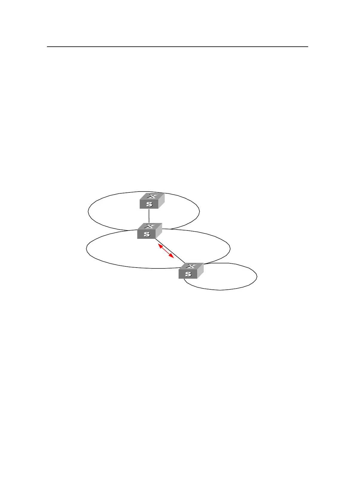
As shown in Figure 4-4, Area 2 and Area 0 are not directly interconnected. It is
required to use Area 1 as a transition area for interconnecting Area 2 and Area 0.
Correctly configure a virtual link between SwitchB and SwitchC in Area 1.
II. Network diagram
152.1
196.1.1.2/24
Sw itc h A
1.1.1.1
Sw itc h B
2.2.2.2
Virtual
link
197.1.1.2/24
.1.1/24
Area 2
Area 1
Area 0
Sw itc h C
3.3.3.3
197.1.1.1/24
196.1.1.1/24
152.1
196.1.1.2/24
Sw itc h A
1.1.1.1
Sw itc h B
2.2.2.2
Virtual
link
197.1.1.2/24
.1.1/24
Area 2
Area 1
Area 0
Sw itc h C
3.3.3.3
197.1.1.1/24
196.1.1.1/24
Figure 4-4 OSPF virtual link configuration
III. Configuration procedure
# Configure SwitchA.
<SwitchA> system-view
[SwitchA] interface Vlan-interface 1
[SwitchA-Vlan-interface1] ip address 196.1.1.1 255.255.255.0
[SwitchA-Vlan-interface1] quit
[SwitchA] router id 1.1.1.1
[SwitchA] ospf
[SwitchA-ospf-1] area 0
[SwitchA-ospf-1-area-0.0.0.0] network 196.1.1.0 0.0.0.255
# Configure SwitchB.
<SwitchB> system-view
[SwitchB] interface vlan-interface 1

 Loading...


