Operation Manual – Routing Protocol
H3C S3600 Series Ethernet Switches-Release 1510 Chapter 5
IP Routing Policy Configuration
5-7
5.5 Displaying IP Routing Policy
After the above configuration, execute the display command in any view to display
and verify the routing policy configuration.
Table 5-5 Display a route policy
Operation Command Description
Display route-policy
information
display route-policy
[ route-policy-name ]
Display address
prefix list information
display ip ip-prefix
[ ip-prefix-name ]
You can execute the display
command in any view.
5.6 IP Routing Policy Configuration Example
5.6.1 Configuring to Filter Received Routing Information
I. Network requirements
SwitchA communicates with SwitchB. OSPF protocol is enabled on both switches.
The router ID of SwitchA is 1.1.1.1 and that of SwitchB is 2.2.2.2.
Configure three static routes and enable OSPF on SwitchA.
By configuring route filtering rules on SwitchA make the three received static routes
partially visible and partially shielded: the routes of network segments 20.0.0.0 and
40.0.0.0 are visible, and the route of network segment 30.0.0.0 is shielded.
View the OSPF routing table to check the routing policy takes effect.
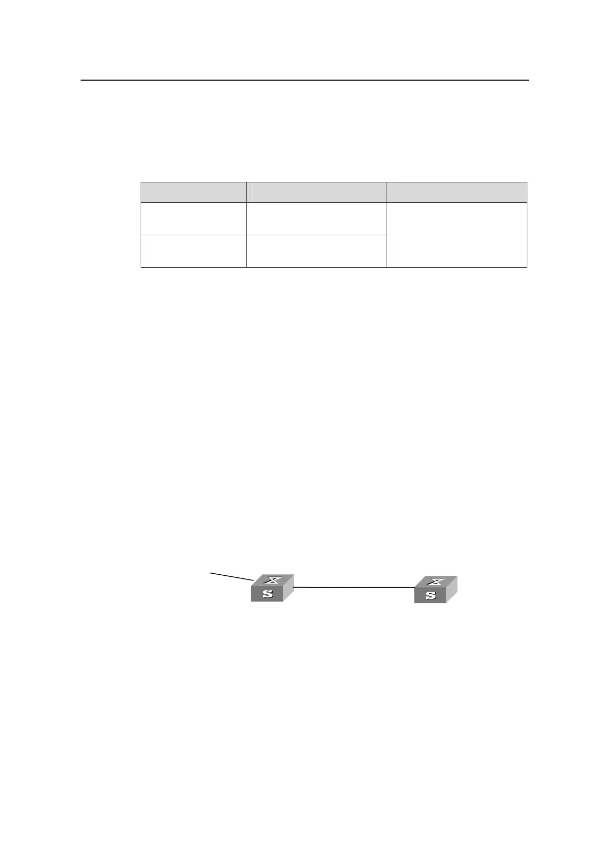
II. Network diagram
area 0
Switch B
static 20.0.0.0/8
30.0.0.0/8
40.0.0.0/8
Router ID:
1.1.1.1
10.0.0.2/8
Switch A
Vlan-interface200
12.0.0.1/8
R
Vlan-interface100
outer ID:
2.2.2.2
10.0.0.1/8
Vlan-interface100
Area 0
Switch B
static 20.0.0.0/8
30.0.0.0/8
40.0.0.0/8
Router ID:
1.1.1.1
10.0.0.2/8
Switch A
Vlan-interface200
12.0.0.1/8
R
Vlan
-interface100
outer ID:
2.2.2.2
10.0.0.1/8
Vlan-interface100
Figure 5-1 Filtering received routing information
III. Configuration procedure
z Configure SwitchA:
# Configure the IP addresses of the interfaces.
<SwitchA> system-view
[SwitchA] interface vlan-interface 100

 Loading...


