Operation Manual – VRRP
H3C S3600 Series Ethernet Switches-Release 1510 Chapter 1
VRRP Configuration
1-11
Table 1-8 Network description
Switch
Ethernet port
connecting to
Host A
IP address of
the VLAN
interface
Switch
priority in the
backup
group
Preemptive
mode
LSW-A Ethernet 1/0/6 202.38.160.1/24 110 Enabled
LSW-B Ethernet 1/0/5 202.38.160.2/24 100 (default) Enabled
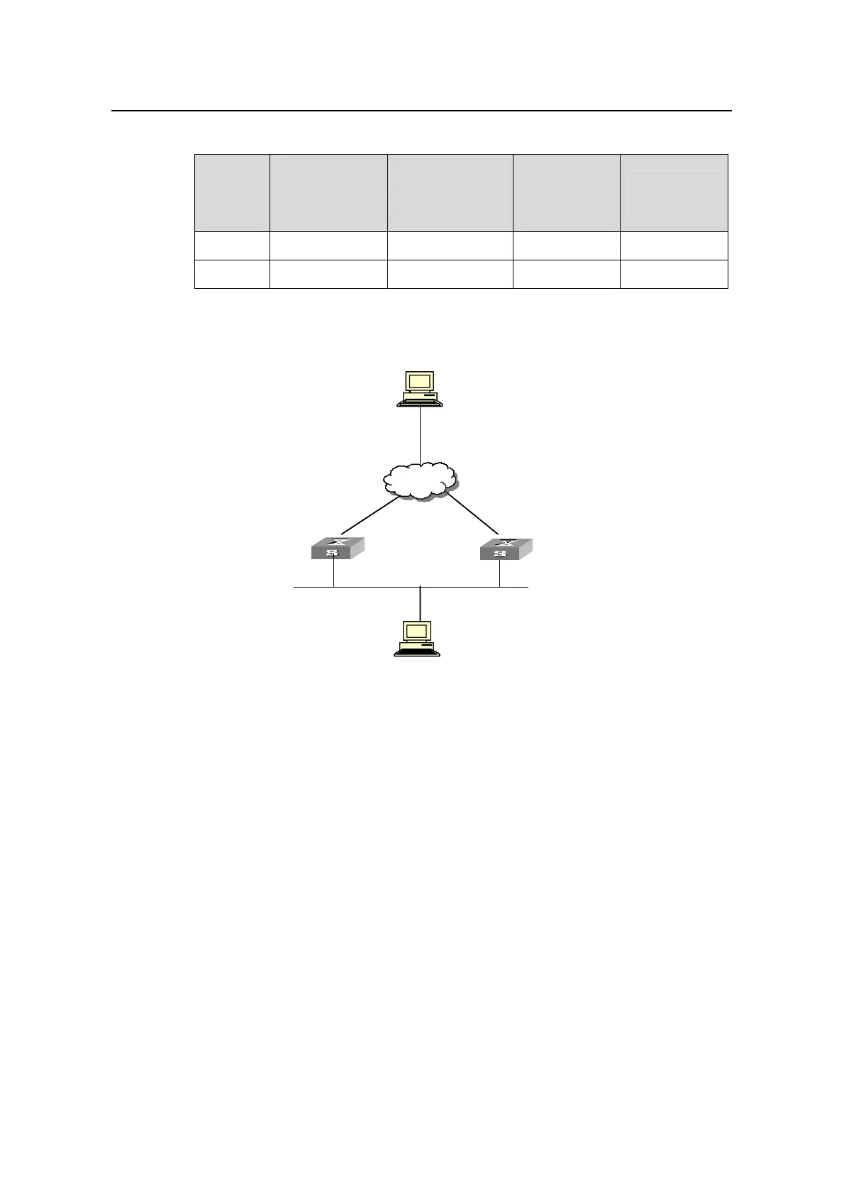
II. Network diagram
Virtual IP address: 202.38.160.111
LSW-A
Host A
202.38.160.3
-Vlan-interface2: 202.38.160.1
Internet
LSW-B
nterface2: 202.38.160.2
-
Vlan-i
Host B
Virtual IP address: 202.38.160.111
Host A
202.38.160.3
-Vlan-interface2: 202.38.160.1
Internet
-
Vlan-interface2: 202.38.160.2
Host B
Virtual IP address: 202.38.160.111
LSW-A
Host A
202.38.160.3
-Vlan-interface2: 202.38.160.1
Internet
LSW-B
nterface2: 202.38.160.2
-
Vlan-i
Host B
Virtual IP address: 202.38.160.111
Host A
202.38.160.3
-Vlan-interface2: 202.38.160.1
Internet
-
Vlan-interface2: 202.38.160.2
Host B
Figure 1-3 Network diagram for single-VRRP backup group configuration
III. Configuration procedure
z Configure Switch A.
# Configure VLAN 2.
<LSW-A> system-view
[LSW-A] vlan 2
[LSW-A-vlan2] port Ethernet 1/0/6
[LSW-A-vlan2] quit
[LSW-A] interface Vlan-interface 2
[LSW-A-Vlan-interface2] ip address 202.38.160.1 255.255.255.0
[LSW-A-Vlan-interface2] quit
# Enable a backup group to respond to ping operations destined for its virtual router IP
address.
[LSW-A] vrrp ping-enable

 Loading...


