Operation Manual – VLAN
H3C S3600 Series Ethernet Switches-Release 1510 Chapter 1
VLAN Overview
1-1
Chapter 1 VLAN Overview
1.1 VLAN Overview
1.1.1 Introduction to VLAN
The traditional Ethernet is a broadcast network, where all hosts are in the same
broadcast domain and connected with each other through hubs or switches. The hub is
a physical layer device without the switching function, so it forwards the received
packet to all ports. The switch is a link layer device which can forward the packet
according to the MAC address of the packet. However, when the switch receives a
broadcast packet or an unknown unicast packet whose MAC address is not included in
the MAC address table of the switch, it will forward the packet to all the ports except the
inbound port of the packet. In this case, a host in the network receives a lot of packets
whose destination is not the host itself. Thus, plenty of bandwidth resources are wasted,
causing potential serious security problems.
The traditional way to isolate broadcast domains is to use routers. However, routers are
expensive and provide few ports, so they cannot subnet the network particularly.
The virtual local area network (VLAN) technology is developed for switches to control
broadcast in LANs.
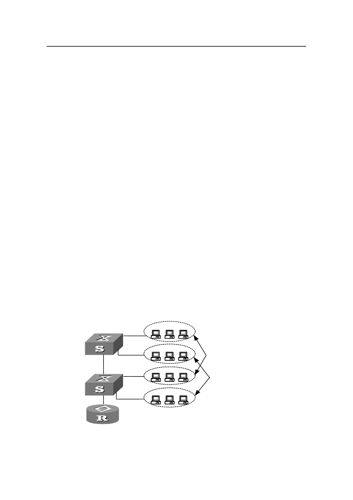
By creating VLANs in a physical LAN, you can divide the LAN into multiple logical LANs,
each of which has a broadcast domain of its own. Hosts in the same VLAN
communicate with each other as if they are in a LAN. However, hosts in different VLANs
cannot communicate with each other directly.
Figure 1-1 illustrates a VLAN
implementation.
VLAN A
VLAN B
VLAN A
VLAN B
VLAN A
VLAN B
LAN Switch
LAN Switch
Router
VLAN A
VLAN B
VLAN A
VLAN B
VLAN A
VLAN B
LAN Switch
LAN Switch
Router
Figure 1-1 A VLAN implementation

 Loading...


