Operation Manual – MSTP
H3C S3600 Series Ethernet Switches-Release 1510 Chapter 1
MSTP Configuration
1-2
1.1.2 Basic MSTP Terminologies
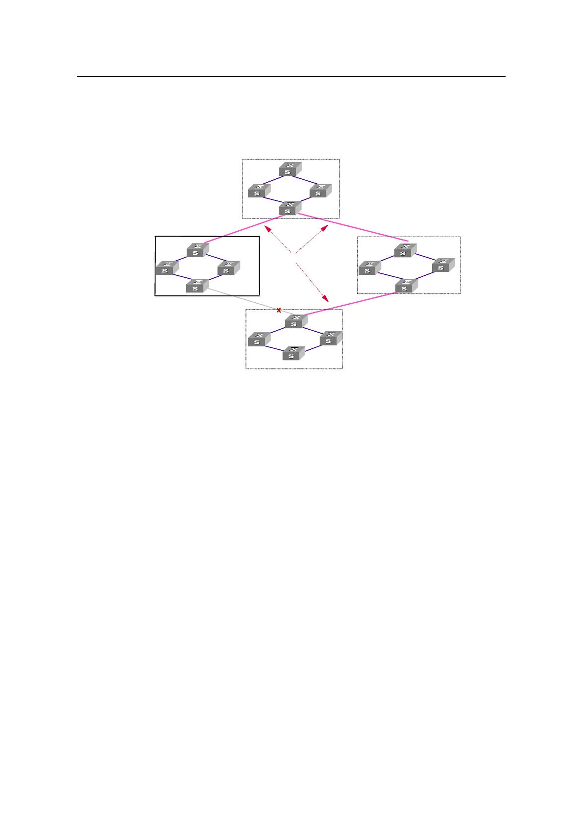
Figure 1-1 illustrates basic MSTP terms (assuming that MSTP is enabled on each
switch in this figure).
Region A0
vlan 1 mapped to Instance 1
vlan 2 mapped to Instance 2
Other vlans mapped to CIST
Region D0
vlan 1 mapping to Instance 1, region root B
vlan 3 mapped to Instance 2 , region root C
Other vlans mapped to CIST
Region B0
vlan 1 mapped to Instance 1
vlan 2 mapped to Instance 2
Other vlans mapped to CIST
Region C0
vlan 1 mapped to Instance 1
vlan 2 and 3 mapped to Instance 2
Other vlans mapped to CIST
C
A
B
D
BPDU
CST: Common
Spanning Tree
CIST: Common and Internal
Spanning Tree
BPDU
BPDU
MSTI: Multiple Spanning
Tree Instance
Figure 1-1 Basic MSTP terminologies
I. MST region
A multiple spanning tree region (MST region) comprises multiple
physically-interconnected MSTP-enabled switches and the corresponding network
segments connected to these switches. These switches have the same region name,
the same VLAN-to-MSTI mapping configuration and the same MSTP revision level.
A switched network can contain multiple MST regions. You can group multiple switches
into one MST region by using the corresponding MSTP configuration commands. For
example, all switches in region A0 shown in
Figure 1-1 have the same MST region
configuration: the same region name, the same VLAN-to-MSTI mappings (that is,
VLAN 1 is mapped to spanning tree instance 1, VLAN 2 is mapped to spanning tree
instance 2, and other VLANs are mapped to CIST), and the same MSTP revision level
(not shown in
Figure 1-1).
II. MSTI
A multiple spanning tree instance (MSTI) refers to a spanning tree in an MST region.
Multiple spanning trees can be established in one MST region. These spanning trees
are independent of each other. For example, each region in
Figure 1-1 contains
multiple spanning trees known as MSTIs. Each of these spanning trees corresponds to
a VLAN.

 Loading...


