Operation Manual – UDP Helper
H3C S3600 Series Ethernet Switches-Release 1510 Chapter 1
UDP Helper Configuration
1-4
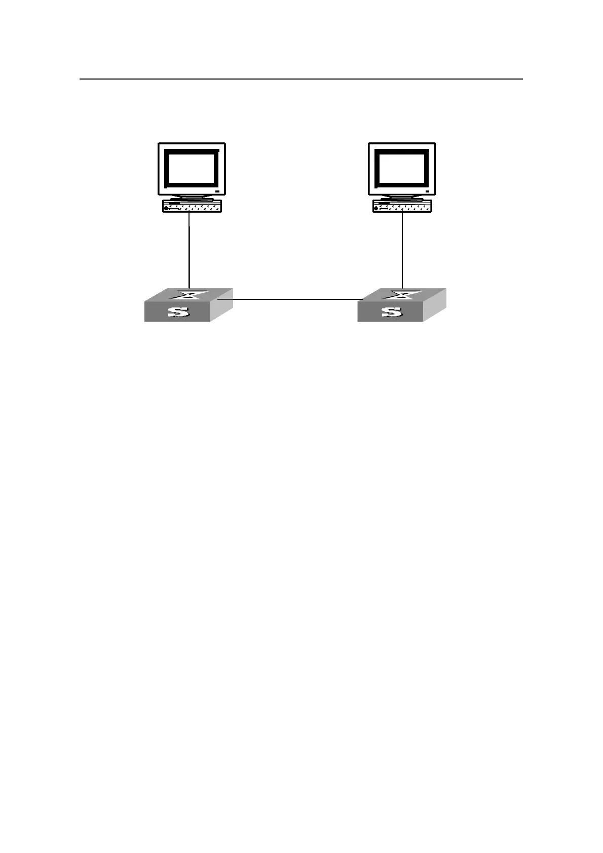
1.4.2 Network diagram
Switch 1
PC1 192.168.1.1
udp
192.168.1.2
PC2 10.2.72.1
Switch 2
10.2.72.39
192.168.1.2
10.2.72.39
Switch 1
PC1 192.168.1.1
192.168.1.2
PC2 10.2.72.1
udp-helper server
Switch 2
10.2.72.39
Switch 1
PC1 192.168.1.1
VLAN interface 20
192.168.1.2
PC2 10.2.72.1
Switch 2
10.2.72.39
192.168.1.2
10.2.72.39
Switch 1
PC1 192.168.1.1
udp
192.168.1.2
PC2 10.2.72.1
Switch 2
10.2.72.39
Switch 1
PC1 192.168.1.1
udp
192.168.1.2
PC2 10.2.72.1
Switch 2
10.2.72.39
192.168.1.2
10.2.72.39
Switch 1
PC1 192.168.1.1
192.168.1.2
PC2 10.2.72.1
udp-helper server
Switch 2
10.2.72.39
Switch 1
PC1 192.168.1.1
VLAN interface 20
192.168.1.2
PC2 10.2.72.1
Switch 2
10.2.72.39
192.168.1.2
10.2.72.39
Figure 1-1 Network diagram for UDP Helper configuration
1.4.3 Configuration procedure
# Enable UDP Helper on Switch1.
<H3C> system-view
[H3C] udp-helper enable
# Specify port 137 to be the UDP port for forwarding UDP broadcast packets. Port 137
is the default UDP port, as prompted in the command line.
[H3C] udp-helper port 137
Port has been configured. Please check the port again.
# Specify the destination server to which UDP packets are to be forwarded.
[H3C] interface Vlan-interface 20
[H3C-Vlan-interface20] udp-helper server 10.2.72.1

 Loading...


