Operation Manual – VRRP
H3C S3600 Series Ethernet Switches-Release 1510 Chapter 1
VRRP Configuration
1-15
1.4.3 Multiple-VRRP Backup Group Configuration
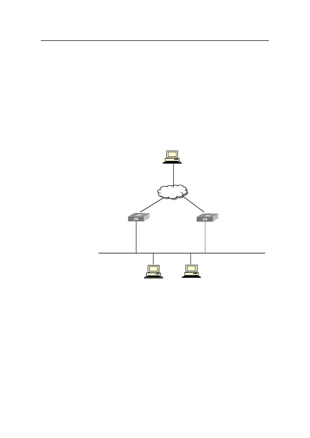
I. Network requirements
A switch can function as backup switches of multiple backup groups.
Multiple-backup group configuration can implement load balancing. For example,
Switch A operates as the master switch of backup group 1 and a backup switch in
backup group 2. Similarly, Switch B operates as the master switch of backup group 2
and a backup switch in backup group 1. Some hosts in the network take virtual router 1
as the gateway, while others take virtual router 2 as the gateway. In this way, both load
balancing and mutual backup are implemented.
II. Network diagram
Backup goup 1:
Virtual IP address: 202.38.160.111
Switch_A
202.38.160.3
-Vlan -interf ace2: 202.38.160.1
Internet
Sw
-
Vlan -int
-
Vlan -interface3: 10.100.10.2
itch_B
erface2: 202.38.160.2
Host B
10.2.3.1
Backup goup
Virtual IP
2:
address: 202.38.160.112
Backup goup 1:
Virtual IP address: 202.38.160.111
Switch_A
Host AHost A
202.38.160.4
-Vlan -interf ace2: 202.38.160.1
Internet
Sw
-
Vlan -int
-
Vlan -interface3: 10.100.10.2
itch_B
erface2: 202.38.160.2
Host B
10.2.3.1
Backup goup
Virtual IP
2:
address: 202.38.160.112
Host C
Backup goup 1:
Virtual IP address: 202.38.160.111
Switch_A
202.38.160.3
-Vlan -interf ace2: 202.38.160.1
Internet
Sw
-
Vlan -int
-
Vlan -interface3: 10.100.10.2
itch_B
erface2: 202.38.160.2
Host B
10.2.3.1
Backup goup
Virtual IP
2:
address: 202.38.160.112
Backup goup 1:
Virtual IP address: 202.38.160.111
Switch_A
Host AHost AHost AHost A
202.38.160.4
-Vlan -interf ace2: 202.38.160.1
Internet
Sw
-
Vlan -int
-
Vlan -interface3: 10.100.10.2
itch_B
erface2: 202.38.160.2
Host B
10.2.3.1
Backup goup
Virtual IP
2:
address: 202.38.160.112
Host C
Figure 1-5 Network diagram for multiple-VRRP backup group configuration
III. Configuration procedure
z Configure Switch A.
# Configure VLAN 2.
<LSW-A> system-view
System View: return to User View with Ctrl+Z.
[LSW-A] vlan 2
[LSW-A-vlan2] port Ethernet 1/0/6
[LSW-A-vlan2] quit
[LSW-A] interface Vlan-interface 2
[LSW-A-Vlan-interface2] ip address 202.38.160.1 255.255.255.0

 Loading...


