Operation Manual – Routing Protocol
H3C S3600 Series Ethernet Switches-Release 1510 Chapter 4
OSPF Configuration
4-28
4.9 OSPF Configuration Example
4.9.1 Configuring DR Election Based on OSPF Priority
I. Network requirements
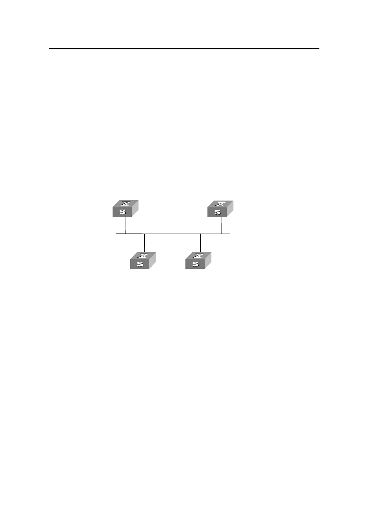
Four S3600 switches, SwitchA, SwitchB, SwitchC, and SwitchD, which run OSPF, are
on the same segment, as shown in
Figure 4-3. Perform proper configurations to make
SwitchA and SwitchC become DR and BDR respectively. Set the priority of SwitchA to
100 (the highest on the network) so that SwitchA is elected as the DR. Set the priority
of SwitchC to 2 (the second highest priority) so that SwitchC is elected as the BDR.
Set the priority of SwitchB to 0 so that SwitchB cannot be elected as the DR. No
priority is set for SwitchD so it has a default priority of 1.
II. Network diagram
BDR
196.1.1.4/24
196.1.1.3/24
Sw itc h A
itch D
1.1.1.1
4.4.4.4
3.3.3.3
196.1.1.2/24
DR
Sw
Sw itc h B
Sw itc h C
2.2.2.2
196.1.1.1/24
BDR
196.1.1.4/24
196.1.1.3/24
Sw itc h A
itch D
1.1.1.1
4.4.4.4
3.3.3.3
196.1.1.2/24
DR
Sw
Sw itc h B
Sw itc h C
2.2.2.2
196.1.1.1/24
Figure 4-3 DR election based on OSPF priority
III. Configuration procedure
# Configure SwitchA.
<SwitchA> system-view
[SwitchA] interface Vlan-interface 1
[SwitchA-Vlan-interface1] ip address 196.1.1.1 255.255.255.0
[SwitchA-Vlan-interface1] ospf dr-priority 100
[SwitchA-Vlan-interface1] quit
[SwitchA] router id 1.1.1.1
[SwitchA] ospf
[SwitchA-ospf-1] area 0
[SwitchA-ospf-1-area-0.0.0.0] network 196.1.1.0 0.0.0.255
# Configure SwitchB.
<SwitchB> system-view
[SwitchB] interface Vlan-interface 1
[SwitchB-Vlan-interface1] ip address 196.1.1.2 255.255.255.0
[SwitchB-Vlan-interface1] ospf dr-priority 0

 Loading...


