Operation Manual – MSTP
H3C S3600 Series Ethernet Switches-Release 1510 Chapter 1
MSTP Configuration
1-45
1.10 MSTP Configuration Example
I. Network requirements
Implement MSTP in the network shown in Figure 1-7 to enable packets of different
VLANs to be forwarded along different spanning tree instances. The detailed
configurations are as follows:
z All switches in the network belong to the same MST region.
z Packets of VLAN 10, VLAN 30, VLAN 40, and VLAN 20 are forwarded along
spanning tree instance 1, instance 3, instance 4, and instance 0 respectively.
In this network, Switch A and Switch B operate on the convergence layer; Switch C and
Switch D operate on the access layer. VLAN 10 and VLAN 30 are limited in the
convergence layer and VLAN 40 is limited in the access layer. Switch A and Switch B
are configured as the root bridges of spanning tree instance 1 and spanning tree
instance 3 respectively. Switch C is configured as the root bridge of spanning tree
instance 4.
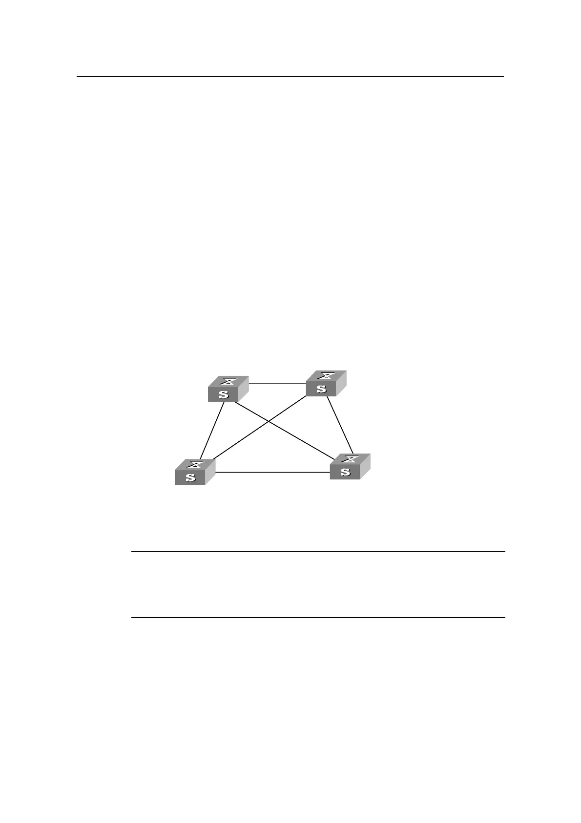
II. Network diagram
Switch A
Switch C
Switch B
Switch D
Permit :
VLAN 10, 20
Permit :
VLAN 10, 20
Permit :
VLAN 20, 30
Permit :
VLAN 20, 30
Permit :all VLAN
Permit :VLAN 20, 40
Switch A
Switch C
Switch B
Switch D
Permit :
VLAN 10, 20
Permit :
VLAN 10, 20
Permit :
VLAN 20, 30
Permit :
VLAN 20, 30
Permit :all VLAN
Permit :VLAN 20, 40
Figure 1-7 Network diagram for MSTP configuration
Note:
The word “permit” shown in Figure 1-7 means the corresponding link permits packets of
specific VLANs.
III. Configuration procedure
1) Configure Switch A
# Enter MST region view.
<H3C> system-view
[H3C] stp region-configuration

 Loading...


