Operation Manual – Mirroring
H3C S3600 Series Ethernet Switches-Release 1510 Chapter 1
Mirroring Configuration
1-14
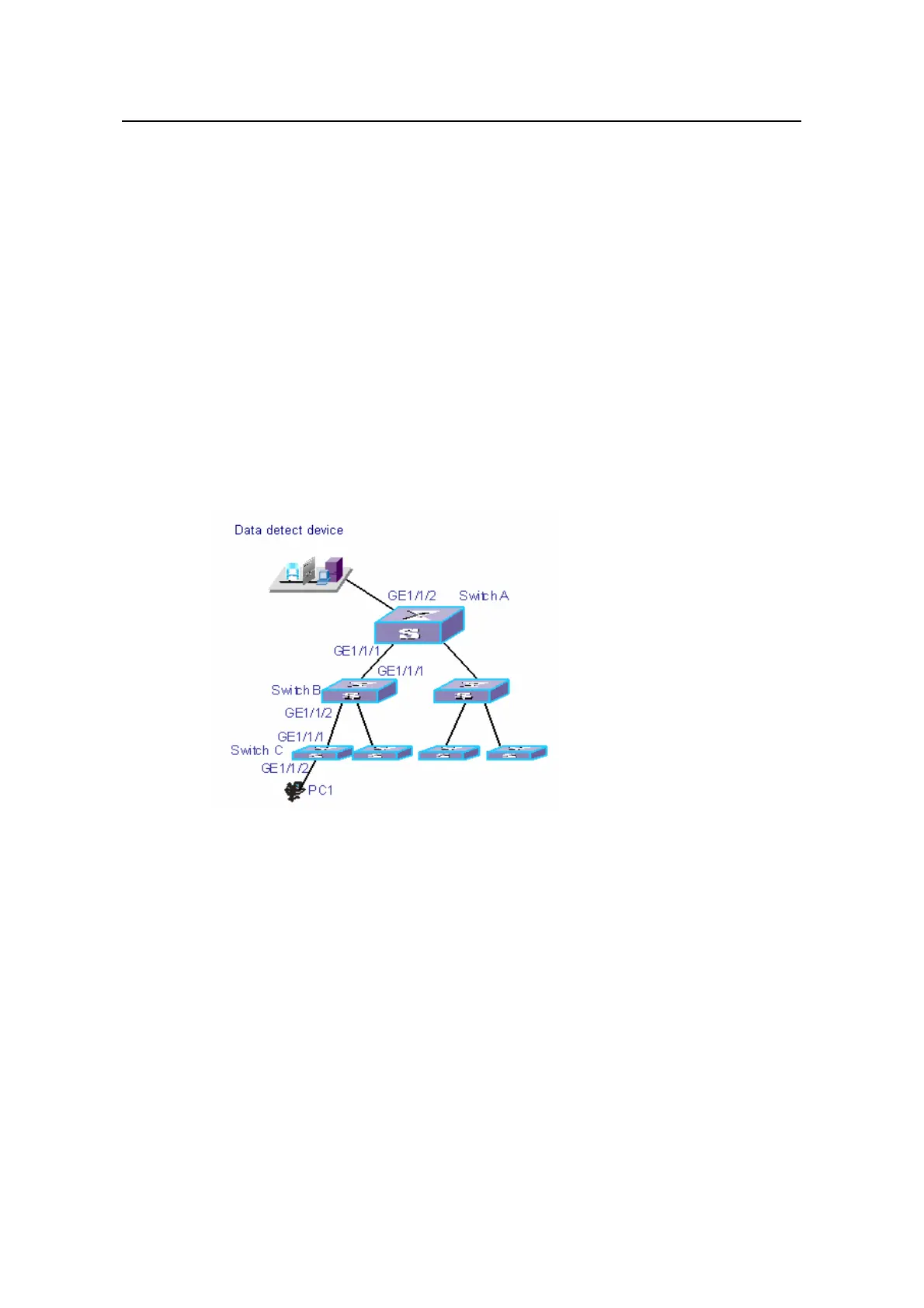
The purpose is to use the data detect device to monitor and analyze the packets sent
by PC1.
To meet the above purpose by using the RSPAN function, perform the following
configuration:
z Define VLAN10 as the remote-probe VLAN.
z Define Switch A as the destination switch; configure GigabitEthernet 1/1/2, the
port that is connected to the data detect device, as the destination port for remote
mirroring. Set GigabitEthernet1/1/2 to an Access port, with STP and LACP
functions disabled.
z Define Switch B as the intermediate switch.
z Define Switch C as the source switch, GigabitEthernet 1/1/2 as the source port for
remote mirroring, and GigabitEthernet 1/1/3 as the reflector port. Set
GigabitEthernet 1/1/3 to an Access port, with STP and LACP disabled.
Network diagram:
Figure 1-3 Network diagram for RSPAN
Configuration procedure:
# Configure Switch C.
<H3C> system-view
[H3C] vlan 10
[H3C-vlan10] remote-probe vlan enable
[H3C-vlan10] quit
[H3C] interface GigabitEthernet 1/1/1
[H3C-GigabitEthernet1/1/1] port link-type trunk
[H3C-GigabitEthernet1/1/1] port trunk permit vlan 10
[H3C-GigabitEthernet1/1/1] quit
[H3C] mirroring-group 1 remote-source
[H3C] mirroring-group 1 mirroring-port GigabitEthernet 1/1/2 inbound

 Loading...


